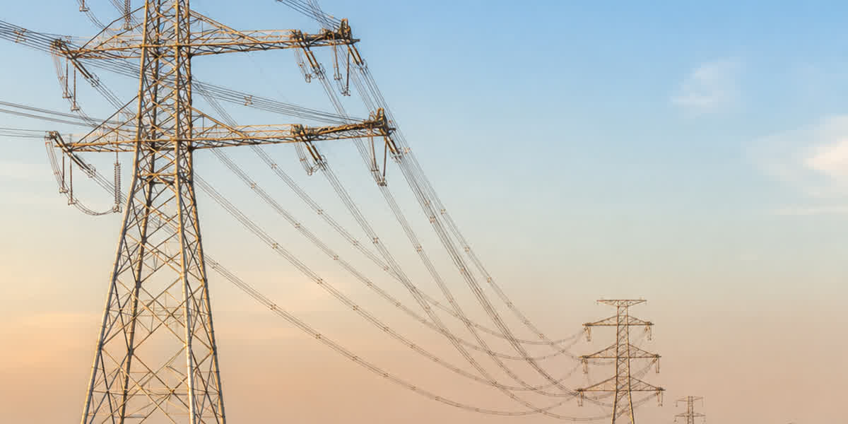
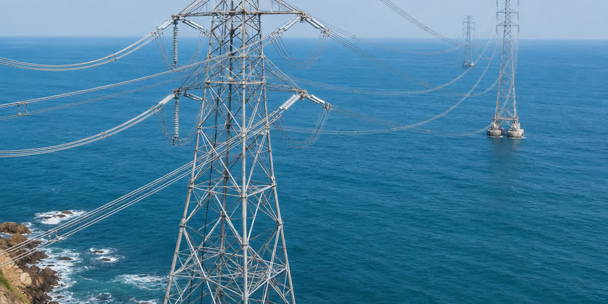
Medium & High Voltage Power Cable Sheath Bonding & Earthing: Metallic Screen Sizing, Circulating Currents, Standing Voltage & Bonding Systems (IEC 60287, IEC 60502-2, IEEE 575)
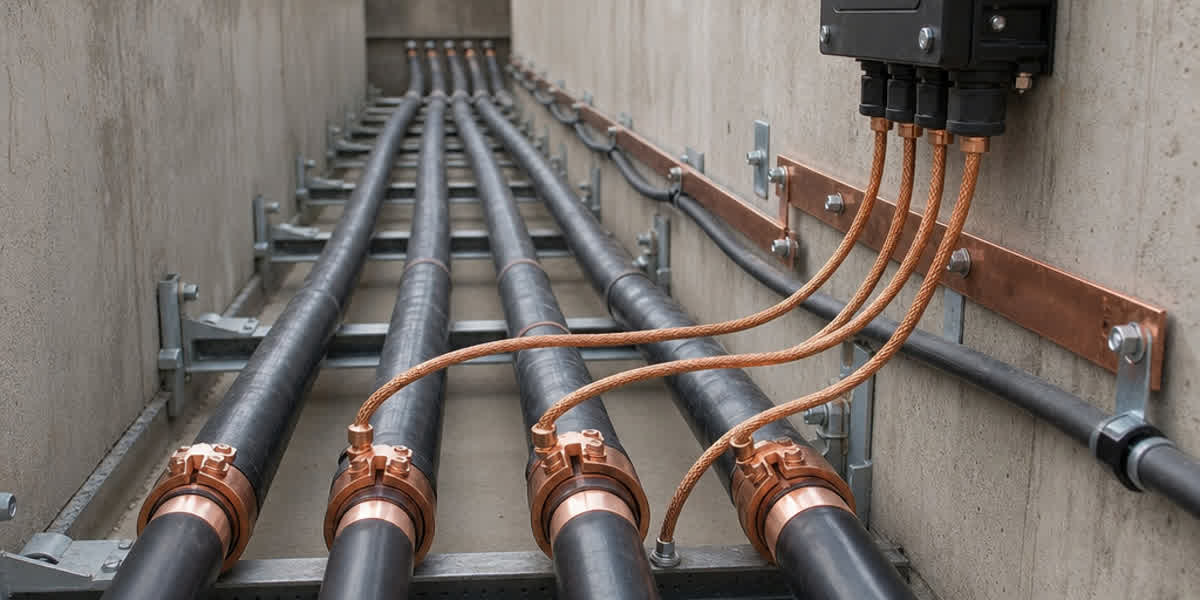
Medium & High Voltage Power Cable Sheath Bonding & Earthing: Metallic Screen Sizing, Circulating Currents, Standing Voltage & Bonding Systems (IEC 60287, IEC 60502-2, IEEE 575)
Medium-voltage (6kV–35kV) and high-voltage (66kV–220kV) single-core power cables are critical lifelines for utility substations, renewable energy collector systems, and heavy industrial distribution networks. However, carrying heavy alternating currents through insulated single-core conductors generates intense time-varying electromagnetic fields that induce longitudinal voltages along the cable's metallic screen or sheath. If the metallic sheath is improperly grounded, engineering teams face a severe operational dilemma: solid bonding at both ends creates closed circulating current loops ($I_{circ}$) that cause massive $I^2R$ heating losses, derating cable ampacity by 10% to 35%, whereas unbonded or single-point bonded arrangements eliminate circulating currents but allow hazardous standing voltages ($E_s$) to build up, threatening human safety and causing sheath overvoltage puncture during system transients.
Selecting the optimal sheath bonding topology—Solid Bonding, Single-Point Bonding, or Cross-Bonding—requires a rigorous engineering analysis balancing thermal derating, standing voltage thresholds, earth fault current withstand, and sheath voltage limiter (SVL) coordination. This comprehensive technical guide details the electromagnetic induction principles, short-circuit screen sizing calculations per IEC 60949, metallic screen material comparisons, sheath bonding system topologies per IEEE 575 and IEC 60287-1-1, and field installation best practices for single-core power cable installations.
1. Electromagnetic Induction in Single-Core Cable Sheaths
In three-core medium-voltage cables, the three phase conductors are enclosed within a common outer boundary, resulting in a symmetrical electromagnetic field where the phasor sum of phase currents equals zero ($\vec{I}_A + \vec{I}_B + \vec{I}_C = 0$). Consequently, mutual induction into the outer metallic sheath is virtually negligible.
In contrast, single-core underground cable circuits feature physically separated phase conductors laid in trefoil (triangular) or flat formations. The alternating magnetic flux produced by each phase conductor links with the metallic screens of adjacent cables, inducing an electromotive force (EMF) along the length of each metallic sheath.
1.1 Mutual Inductance and Induced Standing Voltage
The induced standing voltage per unit length on the metallic screen of a single-core cable is governed by Faraday's law of induction and depends on conductor current, power frequency, and geometrical spacing:
$$E_s = I \cdot X_m = I \cdot 2\pi f \cdot M$$
Where: - $E_s$ = Induced sheath voltage per unit length ($\text{V/km}$) - $I$ = Operating phase current ($\text{A}$) - $f$ = System frequency ($50\text{ Hz}$ or $60\text{ Hz}$) - $M$ = Mutual inductance between conductor and sheath ($\text{H/km}$) - $X_m$ = Mutual reactance ($\Omega\text{/km}$)
For three single-core cables laid in trefoil formation with axial center-to-center spacing $S$ and mean sheath radius $r_s$, the mutual reactance is uniform across all three phases:
$$X_m = 2\pi f \cdot 2 \times 10^{-4} \cdot \ln\left(\frac{S}{r_s}\right) \quad (\Omega\text{/km})$$
For cables laid in flat touching or spaced formation, the mutual inductance between phases is asymmetrical, causing unequal induced voltages between the outer phases and the center phase unless transpositions or cross-bonding schemes are implemented.
1.2 The Engineering Dilemma: Circulating Currents vs. Standing Voltage
The grounding configuration directly dictates how induced voltages manifest:
- Both Ends Grounded (Solid Bonding): A closed electrical loop is formed through the metallic screens and the earth return path. The induced voltage drives continuous sheath circulating currents ($I_{circ}$) that can reach 30% to 70% of the main conductor current. These circulating currents dissipate continuous Joule heat ($P_{loss} = I_{circ}^2 \cdot R_{sheath}$), raising the cable operating temperature and forcing a mandatory conductor ampacity derating per IEC 60287-1-1.
- One End Grounded (Single-Point Bonding): The circulating current loop is broken ($I_{circ} = 0$), completely eliminating sheath thermal losses and maximizing cable current-carrying capacity. However, the induced voltage accumulates continuously along the line, reaching its maximum standing voltage ($E_{max} = E_s \cdot L$) at the ungrounded remote terminal. Under heavy load or external short-circuit conditions, this voltage can exceed human touch safety limits (typically $50\text{V}$ or $65\text{V}$) and cause flashover across the non-metallic outer oversheath.
2. Metallic Screen Sizing & Short-Circuit Thermal Ratings (IEC 60949)
The metallic screen or sheath must fulfill two distinct engineering functions: carrying steady-state capacitive charging currents / low-level induced currents, and safely conducting maximum earth fault currents ($I_k''$) for the duration of substation protection relay clearance ($t_k$) without exceeding the maximum permissible temperature of adjacent XLPE insulation ($250^\circ\text{C}$) or PVC/PE outer jackets ($150^\circ\text{C}$–$200^\circ\text{C}$).
2.1 Adiabatic Short-Circuit Current Formula
Under short-circuit conditions where duration $t \le 3.0\text{ seconds}$, heat transfer to adjacent layers is conservatively neglected (adiabatic condition). The minimum required metallic screen cross-sectional area is calculated according to IEC 60949 and IEC 60502-2:
$$S_{min} = \frac{I_{sc} \cdot \sqrt{t}}{k}$$
Where: - $S_{min}$ = Minimum screen cross-sectional area ($\text{mm}^2$) - $I_{sc}$ = Symmetrical earth fault short-circuit current ($\text{kA}$) - $t$ = Fault clearing duration, including breaker opening time ($\text{s}$) (typically $0.2\text{s}$ to $1.0\text{s}$) - $k$ = Material thermal withstand constant ($\text{A}\cdot\text{s}^{1/2}\text{/mm}^2$)
| Metallic Screen Material | Initial Temperature ($\theta_i$) | Maximum Temperature ($\theta_f$) | Constant $k$ ($\text{A}\cdot\text{s}^{1/2}\text{/mm}^2$) |
|---|---|---|---|
| Plain Copper Wire Screen (CW) | $80^\circ\text{C}$ (under full load) | $250^\circ\text{C}$ | 203 |
| Copper Tape Screen (CT) | $80^\circ\text{C}$ | $200^\circ\text{C}$ | 180 |
| Lead Alloy Sheath (Pb) | $70^\circ\text{C}$ | $150^\circ\text{C}$ | 28 |
| Corrugated Aluminum Sheath (CAS) | $80^\circ\text{C}$ | $200^\circ\text{C}$ | 125 |
⚠️ Design Calculation Example: For an $11\text{kV}$ or $33\text{kV}$ distribution network with a prospective single-phase earth fault of $25\text{kA}$ and protection clearing time of $0.5\text{s}$, the required plain copper wire screen area is: $$S_{min} = \frac{25000 \cdot \sqrt{0.5}}{203} = \frac{25000 \cdot 0.7071}{203} \approx 87.08\text{ mm}^2$$ In this scenario, standard $16\text{ mm}^2$ or $25\text{ mm}^2$ copper tape screens will melt during a line-to-ground fault. A heavy-duty $95\text{ mm}^2$ copper wire screen with counter-helix copper equalizing tape must be specified.
3. Comparative Analysis: Metallic Screen Types and Material Constructions
Cable manufacturers employ different metallic barrier constructions depending on system fault level, mechanical environment, soil corrosivity, and moisture blocking requirements:
| Screen / Sheath Type | Construction Details | Earth Fault Capacity | Radial Moisture Barrier | Mechanical Impact Resistance | Typical Application Sector |
|---|---|---|---|---|---|
| Copper Wire Screen (CWS) | Concentric layer of plain copper wires with reverse binding copper tape | High to Very High ($16\text{mm}^2$–$150\text{mm}^2+$) | Low (Requires swelling water-blocking tapes) | Moderate (Flexible, easy to terminate) | Utility MV/HV distribution, wind farm collector grids, substations |
| Copper Tape Screen (CTS) | Helically applied copper tape with $15\%$–$25\%$ overlap (typically $0.1\text{mm}$ thick) | Low (Limited to electrostatic screening, $3\text{kA}$–$5\text{kA}$ max) | Low | Low (Prone to wrinkling on sharp bends) | Light industrial MV distribution, low-fault secondary substations |
| Corrugated Aluminum Sheath (CAS) | Continuously extruded or welded and corrugated aluminum tube | Extremely High | $100\%$ Impermeable | Maximum (Crush and impact proof) | High-voltage transmission ($66\text{kV}$–$500\text{kV}$), heavy industrial tunnels, subways |
| Lead Alloy Sheath (Pb) | Extruded lead alloy sleeve (Type E or 1/2C per BS 801) | Moderate (Due to lower conductivity, requires greater thickness) | $100\%$ Impermeable (Resistant to hydrocarbons & petrochemicals) | High (Vibration & chemical resistant) | Petrochemical refineries, oil & gas offshore facilities, contaminated soil direct burial |
In specialized industrial control systems, similar shielding topologies are implemented on multi-pair control cable to eliminate electromagnetic interference (EMI) and cross-talk from adjacent heavy power cables.
4. Sheath Bonding System Topologies: Principles & Selection Criteria
IEEE Std 575 (IEEE Guide for the Application of Sheath-Bonding Methods for Single-Core Power Cable Systems) and CIGRE Working Group B1.18 classify single-core cable sheath bonding into three major categories:
[ Solid Bonding (Both Ends Grounded) ]
Terminal A (Grounded) ================================= Terminal B (Grounded)
  -> Zero standing voltage; high circulating currents; thermal derating required.

[ Single-Point Bonding (One End Grounded) ]
Terminal A (Grounded) ================================= Terminal B (Open + SVL)
  -> Zero circulating current; 100% ampacity; standing voltage accumulates at Terminal B.

[ Sectionalized Cross-Bonding (3 Equal Minor Sections) ]
Section 1 [Phase A] ---\ /--- Section 2 [Phase B] ---\ /--- Section 3 [Phase C] === (Grounded)
Section 1 [Phase B] -----X--- Section 2 [Phase C] -----X--- Section 3 [Phase A] === (Grounded)
Section 1 [Phase C] ---/ \--- Section 2 [Phase A] ---/ \--- Section 3 [Phase B] === (Grounded)
  -> Phasor cancellation: Va + Vb + Vc = 0; circulating current approx. zero; voltage limited.
4.1 Topology 1: Solid Bonding (Both Ends Grounded)
In a solidly bonded arrangement, the metallic screens of all three single-core cables are bonded together and connected to the substation earth grid at both terminal ends.
- Operating Characteristics: The standing voltage is clamped to ground potential ($0\text{V}$) at both ends. Circulating currents flow unimpeded through the sheath loop.
- Circuit Length Applicability: Short cable runs (typically $< 300\text{–}500\text{ meters}$) where total thermal loss is acceptable, or low-current circuits where induced voltage is minor.
- Ampacity Impact: Requires derating the continuous conductor rating by $10\%$ to $30\%$ depending on cable spacing. For high-current circuits ($> 800\text{A}$), solid bonding is thermally inefficient.
4.2 Topology 2: Single-Point Bonding
In single-point bonding, the cable screens are bonded and grounded at only one point—usually at the sending-end substation or at the route midpoint (mid-point bonding).
- Operating Characteristics: Eliminates circulating currents completely, allowing 100% of the conductor's thermal capacity to be utilized.
- Standing Voltage Limitation: IEEE 575 and IEC 60502-2 mandate that the steady-state standing voltage at the ungrounded end must not exceed $50\text{V}$ or $65\text{V}$ under normal continuous operating current. Under external system short-circuit faults, the transient standing voltage must remain below the impulse withstand level of the cable oversheath (typically $< 5\text{kV}$ to $10\text{kV}$).
- Sheath Voltage Limiter (SVL): An SVL (zinc-oxide non-linear surge arrester) is installed at the open end inside a link box to clamp transient overvoltages caused by lightning or switching surges, discharging surge energy safely to earth.
- Earth Continuity Conductor (ECC): A parallel insulated ground conductor (ECC) must be installed alongside the power cables to provide an unbroken return path for ground fault currents between the substations without passing fault energy through the single-point screen.
4.3 Topology 3: Sectionalized Cross-Bonding
For long-distance transmission and distribution circuits ($> 1\text{–}2\text{ km}$), cross-bonding is the premier engineering solution.
- System Structure: A major transmission section is divided into three equal minor sections. At each joint bay, the metallic screens of the three phases are cross-connected: Phase A screen connects to Phase B screen in the next section, Phase B connects to Phase C, and Phase C connects to Phase A.
- Phasor Cancellation Mechanism: Because the induced voltages in the three minor sections have equal magnitude but a $120^\circ$ phase displacement, the total induced EMF around the complete major section sums vectorially to zero: $$\vec{E}{total} = \vec{E}} + \vec{E{B} + \vec{E} = 0$$
- Engineering Advantage: Sheath circulating currents are reduced to near zero ($< 3\%$), full conductor ampacity is maintained, and standing voltages at each cross-bonding joint box are restricted to safe operational limits ($< 50\text{V}$).
5. Engineering Selection Matrix: Choosing the Right Bonding Strategy
| Parameter / Requirement | Solid Bonding | Single-Point Bonding | Mid-Point Single Bonding | Sectionalized Cross-Bonding |
|---|---|---|---|---|
| Typical Route Length | $< 300\text{ m}$ | $300\text{ m} - 1000\text{ m}$ | $600\text{ m} - 2000\text{ m}$ | $> 1500\text{ m}$ (in multiples of 3 sections) |
| Circulating Current Loss | High ($10\%\text{–}35\%$ derating) | Zero ($0\%$) | Zero ($0\%$) | Minimal ($< 3\%$) |
| Max Standing Voltage | $0\text{V}$ | At remote open end ($< 65\text{V}$) | At both route ends ($< 65\text{V}$) | At cross-bonding joint boxes ($< 65\text{V}$) |
| Requires SVL Arrester? | No | Yes (at open terminal) | Yes (at both ends) | Yes (at cross-bonding link boxes) |
| Requires Parallel ECC? | No (screen carries fault) | Yes (Mandatory) | Yes (Mandatory) | Optional (depends on fault study) |
| Installation Complexity | Low | Moderate | Moderate | High (requires link boxes & transpositions) |
| Capital Cost | Lowest | Medium | Medium | Higher initial equipment cost |
| Primary Applications | Substation tails, transformer-to-switchgear links | Feeder lines ($0.5\text{–}1.2\text{km}$), wind farm collector risers | Medium utility runs | Major MV/HV underground transmission grids |
6. Hardware, Earthing Accessories & Field Installation Engineering
Reliable sheath bonding systems depend on robust mechanical and electrical connections. Inferior termination hardware or high-resistance earthing connections lead to localized overheating, shield flashover, and catastrophic phase-to-ground faults.
+-------------------------------------------------------------------------+
|                  SINGLE-POINT BONDING SCHEMATIC                         |
|                                                                         |
|  [ SUBSTATION A ]                                   [ SUBSTATION B ]    |
|   Grounded End                                        Isolated End      |
|  +-------------+                                     +-------------+    |
|  | Cable Lugs  |=====================================| Cable Lugs  |    |
|  | (Screen Grd)|-------------------//----------------| (Open Screen|    |
|  +------+------+                                     +------+------+    |
|         |                                                   |           |
|         v (Direct Solid Earth)                              v           |
|    ===========                                         [ Link Box ]     |
|    Earth Grid                                          |   (SVL)  |     |
|         ^                                              +----+-----+     |
|         |                     Parallel ECC Wire             |           |
|         +---------------------------------------------------+           |
|                                                             v           |
|                                                        ===========      |
|                                                        Earth Grid       |
+-------------------------------------------------------------------------+
6.1 Screen Termination and Heavy-Duty Cable Lugs
At termination points, copper wire screens must be gathered into a uniform tail, sealed with semi-conductive break-out boots and water-swellable mastic, and crimped using heavy-duty, high-conductivity tin-plated copper cable lugs conforming to IEC 61238-1 Class A. Bolted connections to the earth busbar must utilize stainless steel hardware with Belleville disc spring washers to maintain constant contact pressure under thermal cycling.
6.2 Trefoil Clamps and Dynamic Short-Circuit Restraints
When single-core cables carry heavy fault currents, the electromagnetic forces between parallel conductors create severe dynamic repulsive forces:
$$F_s = \frac{0.2 \cdot I_{sc}^2}{S} \quad (\text{N/m})$$
To prevent physical whipping and oversheath abrasion, non-magnetic aluminum or composite trefoil clamps from our fittings & hardware catalog must be installed at strictly calculated intervals (typically $0.8\text{m}$ to $1.5\text{m}$, tightened to calibrated torque values per IEC 61914).
6.3 Link Boxes and Sheath Voltage Limiters (SVL)
For single-point and cross-bonded systems, link boxes must be rated to IP67 or IP68 for direct burial or vault installation. Zinc-oxide (ZnO) SVLs must be selected with a continuous operating voltage ($U_c$) exceeding the maximum power-frequency standing voltage under full load, combined with a residual voltage low enough to protect the cable's non-metallic outer jacket (tested to DC $10\text{kV}$ for 1 minute per IEC 60502-2 / IEC 60229).
7. Field Quality Assurance: Commissioning & Sheath Integrity Testing
Before commissioning any medium or high-voltage single-core cable system, the integrity of the sheath isolation must be verified through rigorous field testing:
- Oversheath DC Voltage Withstand Test (IEC 60229 / IEEE 400): Apply a DC test voltage of $4\text{kV}$ per $1.0\text{mm}$ of outer sheath thickness (maximum $10\text{kV}\text{ DC}$) between the metallic screen and surrounding earth for $1.0\text{ minute}$. Leakage current must remain stable with zero breakdown.
- SVL Disconnection and Insulation Resistance: Disconnect the SVL link bar and verify screen-to-earth insulation resistance with a $2.5\text{kV}$ or $5\text{kV}$ megohmmeter (minimum acceptable value: $100\text{ M}\Omega\cdot\text{km}$).
- Circulating Current Ratio Measurement: Energize the circuit under balanced load and measure screen circulating currents with a high-accuracy Rogowski coil or True-RMS clamp meter. In single-point and cross-bonded systems, sheath current must be $< 3\%$ of phase current.
8. Manufacturing Excellence & Custom Engineering by SiTong Cable
At Zhengzhou Sitong Cable Co., Ltd. (SiTong Cable / 郑州四通电缆), we engineer and manufacture premium-grade medium and high-voltage power cables (6kV up to 220kV) tailored to demanding utility, industrial, and renewable energy specifications:
- Triple-Extrusion CCV Lines: Continuous catenary vulcanization (CCV) lines with fully enclosed cleanroom material handling ensure microscopic purity, super-smooth semi-conductive conductor and insulation shields, and zero micro-voids in cross-linked polyethylene (XLPE) insulation.
- Custom Metallic Screen Configurations: We manufacture custom plain copper wire screens with cross-sectional areas from $16\text{mm}^2$ up to $150\text{mm}^2+$, helically wrapped with counter-helix copper equalizing tapes, heavy copper tape shields, seamless extruded lead alloy sheaths, and longitudinal corrugated aluminum sheaths.
- Comprehensive Quality Certification: Our power cables are certified under ISO 9001, ISO 14001, ISO 45001, CE, and tested in accordance with IEC 60502-2, IEC 60840, IEC 60949, BS 6622, and IEEE 575.
Frequently Asked Questions (FAQ)
Q1: Why is solid bonding unsuitable for long, high-current single-core cable routes?
A: In single-core cables carrying high current (e.g., $> 600\text{A}$–$1000\text{A}$), solid bonding creates a low-impedance closed loop through the metallic screen. The induced voltage drives heavy circulating currents ($I_{circ}$) that generate continuous $I^2R$ resistive heating inside the screen. This additional thermal load raises the cable core temperature, forcing engineers to derate the cable's current-carrying capacity by $15\%$ to $35\%$. Over a long route, this represents severe energy waste and necessitates oversizing the conductor cross-section.
Q2: What is the maximum allowable standing voltage on an ungrounded cable sheath?
A: Under normal continuous rated load, IEEE Std 575 and IEC 60502-2 recommend limiting the maximum standing touch voltage to $50\text{V}$ or $65\text{V}$ at accessible terminal link boxes to prevent lethal shock hazard to personnel. Under maximum system phase-to-ground short-circuit fault conditions, the transient standing voltage is permitted to reach several kilovolts (typically $< 5\text{kV}$), provided that a Sheath Voltage Limiter (SVL) is installed and the cable outer oversheath withstands the transient impulse without dielectric puncture.
Q3: How do I choose between Copper Wire Screen (CWS) and Copper Tape Screen (CTS)?
A: The choice is governed by the network's prospective single-phase earth fault current ($I_{sc}$) and fault clearing time ($t$). Copper tape screens have a small effective cross-sectional area and higher contact resistance between overlapping wraps, limiting their short-circuit withstand to approximately $3\text{kA}$–$5\text{kA}$ for $0.5\text{s}$. For utility networks with earth fault levels exceeding $10\text{kA}$–$25\text{kA}$, heavy-duty Copper Wire Screens ($35\text{mm}^2$–$95\text{mm}^2+$) must be specified per IEC 60949 calculations to prevent explosive thermal destruction during a line-to-ground fault.
Q4: Why is an Earth Continuity Conductor (ECC) mandatory in single-point bonded installations?
A: In a single-point bonded system, the metallic screen is isolated at one end and cannot carry ground return fault currents back to the source substation. If an earth fault occurs outside the cable system, fault current attempting to return through the earth could encounter high ground resistance, elevating local touch potentials. A dedicated, insulated Earth Continuity Conductor (ECC) laid in parallel with the single-core cables provides a guaranteed low-impedance return path, ensuring immediate clearance by protection relays.
Q5: When is Sectionalized Cross-Bonding required instead of Single-Point Bonding?
A: When the cable route length exceeds approximately $1.0\text{ to }1.5\text{ kilometers}$, the induced standing voltage at the open end of a single-point bonded circuit will exceed the permissible $50\text{V}$–$65\text{V}$ continuous safety threshold. Cross-bonding divides the long feeder into multiples of three balanced minor sections, vectorially canceling the induced voltages while keeping maximum standing voltages well below safe limits at every intermediate joint bay.
Related Engineering Resources & Product Catalogs
👉 Browse our High-Performance Medium & High Voltage Power Cable Range
👉 Explore Heavy-Duty Underground Direct Burial & Armoured Cables
👉 Contact SiTong Cable Technical Engineering Team for Custom Cable Sizing & Bonding Design
📬 Sales & Engineering Inquiries: sales@sitongcable.com | 📞 Phone: +86-371-69176007
🏢 Zhengzhou Sitong Cable Co., Ltd. (郑州四通电缆) | Dedicated to Global Grid Reliability & Engineering Precision