Control Cable Installation & Maintenance: Complete Field Guide for Industrial Automation & Instrumentation Systems

2026-07-31 | SiTong Cable | technical
Control Cable Installation & Maintenance: Complete Field Guide for Industrial Automation & Instrumentation Systems

Control Cable Installation & Maintenance: Complete Field Guide for Industrial Automation & Instrumentation Systems

Control cables carry the signals that run modern plants — 4-20 mA process loops, RTD and thermocouple inputs, 24 V DC solenoids, contactor coils and digital I/O. Unlike power cables, their job is not to deliver kilowatts but to deliver millivolts and milliamps without distortion. That is why installation practice matters more for control cable than for almost any other cable type: a 230 V power circuit tolerates a slightly loose terminal, while a 10 mV thermocouple signal does not. This field guide covers pre-installation preparation, engineering calculations, step-by-step installation procedure, post-installation testing, routine maintenance, troubleshooting and safety for control and instrumentation cables, based on IEC 60228, BS 5308, UL 13, UL 1277, NEC 725/727, IEEE 383 and IEEE 1185.

1. Control Cable Types and Application Overview

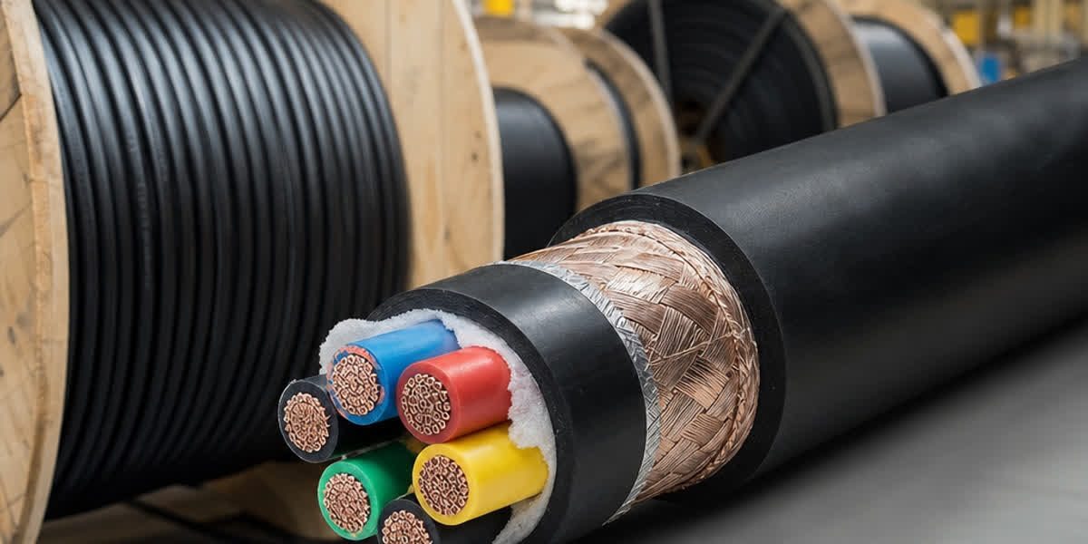
A control cable is a multi-core cable designed to transmit control and instrumentation signals at low voltage (typically 300/500 V, 450/750 V or 0.6/1 kV). The most common constructions are:

Type Construction Typical Application
LiYY / YY PVC insulated, PVC sheathed, unscreened Indoor panel wiring, general control circuits
LiYCY / CY PVC insulated, PVC sheathed, copper braid screened Analog instrumentation, VFD and frequency converter signals
SY PVC insulated, PVC sheathed, steel wire braid screened Mechanical protection, outdoor and plant-floor runs
Instrumentation cable (BS 5308) Twisted pairs/triples, individual + overall screen RTD, thermocouple, 4-20 mA loops, fieldbus
Armored control cable Steel wire or tape armour over core assembly Direct burial, mechanical-risk areas

💡 Rule of thumb: use screened cable (LiYCY/CY or BS 5308 type) for any analog signal below 1 V or any signal run longer than 30 m. Unscreened LiYY is acceptable only for short indoor digital and power-control circuits.

2. Pre-Installation Preparation

2.1 Receiving and Storage Checklist

Check Acceptance Criteria
Drum condition No broken flanges; end caps fitted and sealed
Sheath visual inspection No cuts, chafing or crush marks; no water stains
Length verification Drum label length matches delivery note
Megger test on receipt ≥ 100 MΩ at 500 V DC between cores and core-to-screen
Storage environment Dry, indoor, 0–40 °C; drums on bearers, not on the ground
Shelf life PVC sheath: store within 2 years of manufacture if UV-exposed

Moisture is the number one enemy of control cable. If a drum has been stored outdoors without end caps, do not install it until a full insulation resistance test has been performed.

2.2 Tools and Equipment Checklist

Tool Category Items Application
Pulling Cable rollers, pulling stockings/grips, swivels, tension dynamometer, lubricant Damage-free pulling
Termination Cable strippers, side cutters, crimping tool, torque screwdriver, gland spanners Glanding and termination
Testing 500 V DC insulation tester (megger), multimeter, loop calibrator, continuity tester Post-installation verification
Safety LOTO kit, voltage detector, PPE (gloves, goggles, safety shoes) Safe work practice

2.3 Route Survey and Installation Plan

Walk the route before pulling. Check tray fill, bend locations, crossing points, and available space for the minimum bending radius. Mark pull points and intermediate rollers. For long runs, plan the pull direction so that the cable is pulled from the drum over the top, never from underneath, and so that bends are approached with adequate straight lead-in (at least 10× the cable diameter).

3. Engineering Considerations: Bending Radius, Pulling Tension and Separation

3.1 Minimum Bending Radius

Cable Type Installation During Pulling
Unscreened (LiYY, YY) 6 × OD 10 × OD
Screened (LiYCY, CY, SY) 12 × OD 15 × OD
BS 5308 instrumentation 12 × OD 15 × OD
Armored 12 × OD 15 × OD

Exceeding these limits crushes the pair lay and the screen, increasing capacitance unbalance and degrading noise rejection permanently.

3.2 Pulling Tension and Sidewall Pressure

Maximum pulling tension for a copper-conductor control cable is limited by the conductors:

T_max = N × A × σ where N = number of cores, A = conductor cross-section (mm²), σ = 34.5 MPa (5000 psi) for copper.

For a 12-core × 1.5 mm² cable: T_max = 12 × 1.5 × 34.5 ≈ 620 N (≈ 63 kg). Never exceed this — pulling harder than the conductor limit stretches the copper and creates permanent resistance and capacitance faults. Use a dynamometer on every pull. Where the calculated pull exceeds the limit, install intermediate pulling points or split the run.

Sidewall pressure at any bend must be kept below 730 kg/m (500 lb/ft) per IEEE 1185; use larger-radius rollers or sweep bends at every change of direction.

3.3 Separation from Power Cables

Condition Minimum Separation
Class 2/3 circuits vs power conductors (NEC 725.136) 50 mm (2 in) or a grounded barrier
Type ITC tray cable vs power (NEC 727.4) 50 mm (2 in) or a barrier
Analog signal vs power cable > 30 A 300 mm recommended
Parallel run along a wall/duct, analog signals 300 mm or a steel partition
Crossing at 90° 50 mm (no long parallel exposure)

The 50/60 Hz magnetic field from a power cable induces voltage in a control loop. A 300 mm separation typically reduces the induced noise below the 1 mV level required for reliable analog signals. When segregation is impossible, run the control cable in a separate steel tray or conduit with a continuous grounded bond.

4. Step-by-Step Installation Procedure

Step 1 — Prepare the route. Clean the tray, fit protective rollers at every edge and bend, and install intermediate support rollers every 2–3 m on horizontal runs.

Step 2 — Set up the drum. Mount the drum on a jack with the cable paying off the top. A braking device prevents over-run and snaking.

Step 3 — Pull the cable. Use a pulling stocking over the sheath (never pull on individual cores), attach a swivel, apply approved cable lubricant, and pull at a steady speed of 5–15 m/min while watching the dynamometer. Stop immediately if tension spikes.

Step 4 — Dressing and fixing. Lay the cable with a natural 1–2% service slack to absorb thermal movement. Fix with tray cleats or cable ties at intervals of 300 mm on vertical runs and 400–600 mm on horizontal runs. Do not over-tighten ties — deformation of the sheath compresses the cores.

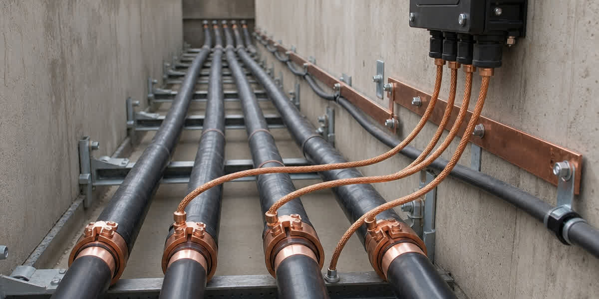
Step 5 — Glanding. Select a gland matched to the cable armour/screen type (e.g., Ex d / Ex e certified glands in hazardous areas per IEC 60079-14). Strip back the sheath with a controlled-depth cutter, fan the screen braid back over the gland cone, and tighten the gland nut to the manufacturer's torque.

Step 6 — Termination. Strip 8–10 mm of insulation, crimp with the correct ferrule (bootlace ferrule for multi-strand), and torque terminals to the panel manufacturer's specification. Leave the spare cores clearly identified and terminated or individually insulated.

Step 7 — Shield grounding. Ground the cable screen at one end only — normally the control room / receiving end. Grounding both ends creates a loop that picks up 50/60 Hz interference. At the field end, insulate the screen and leave it floating or connect it via a small capacitor (0.1 µF) if high-frequency noise is a concern.

Step 8 — Identification. Fit permanent cable markers at both ends, at every 10 m in cable trays, and at every penetration. Record core colours and terminal numbers on the loop schedule.

⚠️ Safety: de-energize and LOTO the circuit before any termination work. Induced voltages on long parallel runs can exceed 50 V even with the circuit de-energized — test before touching.

5. Post-Installation Inspection and Testing

Test Method Acceptance Criteria
Insulation resistance 500 V DC megger, core-to-core and core-to-screen, 1 minute ≥ 100 MΩ per km for new installation; typical readings 1–10 GΩ
Shield continuity Low-resistance ohmmeter end-to-end on the screen ≤ 1 Ω per 100 m for copper braid
Conductor continuity Continuity tester on every core 0 Ω (within meter accuracy); consistent with loop schedule
Polarity / identification Ring-out each core against the schedule No crossed cores
Grounding bond Measure resistance from screen to plant earth at the control end < 1 Ω

Record all readings and keep them for trend comparison — the trend is more valuable than the absolute value. A 30% drop in insulation resistance between two annual tests is an early warning even when the reading is still above the acceptance limit.

6. Routine Maintenance Schedule

Frequency Activity
Monthly Visual inspection of exposed runs; check gland tightness and cable ties
Quarterly Infrared thermography of terminations — any terminal more than 10 °C above ambient indicates a loose connection
Semi-annual 500 V DC insulation test on critical loops; compare against baseline
Annual Shield continuity check; torque verification of panel terminations; loop calibration check on analog signals
Every 3–5 years Full insulation resistance test and trend analysis; replace any cable with cracked or embrittled sheath

7. Troubleshooting Common Issues

Problem Likely Cause Solution
50/60 Hz hum on analog signal Screen grounded at both ends (ground loop) Convert to single-point grounding; check bonding points
Intermittent signal / drift Loose termination or corroded contact Re-terminate with new ferrules; torque to specification
Cross-talk between pairs Excessive capacitance or tight pair coupling Increase separation; verify pair twist integrity at terminations
Low insulation resistance Moisture ingress at gland or damaged sheath Replace gland seals; dry-out and retest; repair or replace sheath
Cable runs hot / voltage drop at load Undersized conductor for the control load Verify load current; upgrade conductor cross-section
Screen braid corroded Aggressive atmosphere (chlorides, H₂S) Use tinned copper braid or armored variant
Sheath cracking UV or chemical exposure Use UV-stable LSZH/PE sheath or route in conduit
Induced voltage on spare cores Long parallel run with power cables Ground spare cores at one end; increase separation

8. Safety Considerations

Hazard Precaution
Induced voltage on long runs Test and ground before handling; treat all cores as live
Live circuits during termination De-energize, LOTO, and verify with a voltage detector
Explosive atmospheres (Ex zones) Certified glands and terminations per IEC 60079-14; hot-work permit
Heavy drums and long pulls Mechanical handling aids; two-person rule; no pulling by hand over edges
Sharp tray edges and copper dust Gloves, goggles, and long sleeves; wash hands after handling
Confined spaces (trenches, pits) Gas test, ventilation, and a standby person before entry

9. FAQ

Q1: Why should the control cable shield be grounded at only one end? Grounding both ends creates a closed loop through which the magnetic field of nearby power cables induces a 50/60 Hz circulating current — exactly the interference the screen was meant to stop. Single-point grounding, normally at the control room end, drains capacitive noise to earth while keeping the loop open. High-frequency applications (fieldbus, Ethernet) are the exception where both ends may be grounded to control radiated emissions.

Q2: What is the minimum bending radius for control cable? Unscreened cable: 6× the outer diameter (10× during pulling). Screened and armored cable: 12× the outer diameter (15× during pulling). Bending tighter than this crushes the screen and pair lay permanently, increasing capacitance and reducing noise immunity.

Q3: How far should control cable be kept from power cable? NEC 725.136 and NEC 727.4 require a minimum of 50 mm (2 in) separation from power conductors unless a grounded barrier is used. For analog signals running parallel to circuits above 30 A, 300 mm separation is recommended to keep induced noise below about 1 mV.

Q4: What insulation resistance is acceptable on a new control cable? A new installation should measure at least 100 MΩ per km at 500 V DC; healthy cables typically read 1–10 GΩ. What matters most is consistency between cores and the trend over time — a 30% annual decline signals developing moisture or insulation degradation.

Q5: Can control cable share a cable tray with power cables? Only with proper segregation: a grounded metal partition, or a minimum 50 mm separation in a ventilated tray, with fill kept below 50% of the tray cross-section per NEC 392.22. Analog and digital control cables should not share a tray compartment with cables above 30 A unless screened and single-point grounded.

10. References and Standards

Standard Description
IEC 60228 Conductors of insulated cables — conductor classes and resistance
IEC 60227 PVC insulated cables, rated voltages up to 450/750 V
IEC 60502-1 Power cables with extruded insulation, 1 kV and 3 kV (0.6/1 kV class)
BS 5308 Instrumentation cables — screened twisted pairs/triples
UL 13 Power-limited circuit cable
UL 1277 Tray cable (Type TC)
NEC 725, 727, 392 Class 2/3 circuits, Type ITC, cable tray fill
IEEE 383 Flame test for cables in nuclear/industrial plants
IEEE 1185 Cable pulling and installation guide
IEC 60332-1/-3 Flame propagation tests (single and bundled)
IEC 61034 / IEC 60754 Smoke density and halogen content
IEC 60079-14 Electrical installations in explosive atmospheres
ICEA S-73-532 Control and instrumentation cable standard
EN 50288 Multi-element metallic cables for analog/digital signals

11. About Sitong Cable

Sitong Cable manufactures control and instrumentation cables to IEC, BS, UL and ASTM standards, with PVC, PE and LSZH sheaths, copper or tinned copper braid screens, and optional steel wire armour — supplied on export-grade drums with full test certificates. Our engineers can help you select the right construction for your process, plant layout and environmental conditions.

👉 Browse our Control Cable product range 👉 Control Cable (Instrumentation & Control Cable): Complete Technical Guide — Standards, Specifications, Selection 👉 Contact our team

📬 Sales inquiries: sales@sitongcable.com | 📞 Phone: +86-371-69176007

This guide was prepared by the Sitong Cable engineering team. All technical data references the standards listed in Section 10.