Substation Grounding Grid Design & Conductor Sizing: Galvanized Steel Wire (GSW) vs. Copper Earth Mats, Touch & Step Voltage Safety, Short-Circuit Thermal Limits, and Soil Resistivity Engineering (IEEE 80, IEC 62561, ASTM A475)
Substation Grounding Grid Design & Conductor Sizing: Galvanized Steel Wire (GSW) vs. Copper Earth Mats, Touch & Step Voltage Safety, Short-Circuit Thermal Limits, and Soil Resistivity Engineering (IEEE 80, IEC 62561, ASTM A475)
Substation grounding grid engineering ensures personnel safety and asset protection against catastrophic phase-to-ground faults. This comprehensive technical guide analyzes Galvanized Steel Wire (GSW) versus copper earth mats under IEEE Std 80, detailing short-circuit thermal sizing ($I^2 t$), touch and step voltage mitigation, soil resistivity modeling, and anti-theft design for modern electrical substations.
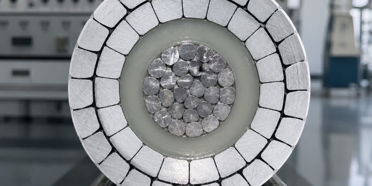
In high-voltage (HV) and extra-high-voltage (EHV) transmission substations, industrial switchyards, and renewable energy collector stations (wind and solar PV), the grounding grid (or earth mat) serves two non-negotiable functions: providing a low-impedance dissipation path for lightning surges and ground-fault currents to prevent dangerous potential rises, and restricting touch voltages ($E_{touch}$) and step voltages ($E_{step}$) to levels tolerable by the human body. Historically, bare electrolytic copper dominated grounding specifications due to its high electrical conductivity. However, severe copper theft vandalism, escalating raw material volatility, and galvanic corrosion of adjacent buried steel foundations have driven international power utilities and EPC contractors toward engineered hot-dip galvanized steel wire strand systems.
Selecting the optimal grounding conductor requires rigorous evaluation of conductor cross-sectional area under asymmetrical fault currents, soil corrosivity parameters, surface layer crushed rock resistivity, and life-cycle asset economics. Specifying high-integrity materials such as galvanized steel wire strand range manufactured to ASTM A475, BS 183, and IEC 60888 ensures that the buried earth mesh maintains mechanical and thermal resilience across 30- to 50-year substation design lifespans.
+----------------------------------------------------------------------------------------------------+
|                         TYPICAL HV SUBSTATION GROUNDING GRID ARCHITECTURE                         |
+----------------------------------------------------------------------------------------------------+
|                                                                                                    |
|    [Lightning Mast / OHGW Shield]                   [Surge Arrester & Power Transformer]          |
|                 |                                                      |                           |
|                 |                                       Heavy Grounding Riser Lead                 |
|                 |                                   (Bimetallic Lugs to Tank Ground)               |
|                 |                                                      |                           |
|   +-------------v------------------------------------------------------v-----------------------+   |
|   | 0.10m - 0.15m Crushed Rock Surface Layer (Resistivity rho_s = 2500 - 5000 Ohm-m)           |   |
|   +--------------------------------------------------------------------------------------------+   |
|   ////////////////////////////// Natural Soil Grade (rho) ////////////////////////////////////   |
|                 |                                                      |                           |
|                 +-----------------------+------------------------------+                           |
|                                         |                                                          |
|   +=====================================v======================================================+   |
|   | MAIN BURIED GROUNDING MESH (Depth h = 0.5m - 0.8m)                                         |   |
|   | High-Strength Galvanized Steel Wire Strand (ASTM A475 Class A/B/C) or Bare Copper Mesh     |   |
|   | Grid Conductors Spaced in Rectangular / Square Meshes (D = 5m to 10m grid spacing)         |   |
|   +==================+=================================================+=======================+   |
|                      |                                                 |                           |
|                      | (Exothermic Weld / Heavy Compression Clamp)     |                           |
|                      v                                                 v                           |
|               [Vertical Ground Rod]                             [Vertical Ground Rod]              |
|               (Galvanized Steel / Copper-Clad)                  (Galvanized Steel / Copper-Clad)   |
|               Driven to Low-Resistivity Soil Layer              Driven to Low-Resistivity Soil     |
|               (Length L_r = 3.0m - 6.0m)                        (Length L_r = 3.0m - 6.0m)         |
|                                                                                                    |
+----------------------------------------------------------------------------------------------------+
1. IEEE Std 80 Conductor Sizing Methodology & Short-Circuit Thermal Limits
The cross-sectional area of any substation grounding conductor must be engineered to withstand the maximum symmetrical ground-fault current without exceeding the permissible thermal threshold or annealing the conductor metal during the fault clearance window.
1.1 The Fundamental IEEE Std 80 Sizing Equation
Under IEEE Std 80 (Clause 11.3.1), the minimum conductor cross-sectional area $A_{mm^2}$ is derived from the thermal energy equation ($I^2 t$):
$$A_{mm^2} = \frac{I_{f}}{\sqrt{\left(\frac{TCAP \cdot 10^{-4}}{t_c \cdot \alpha_r \cdot \rho_r}\right) \ln\left(\frac{K_0 + T_m}{K_0 + T_a}\right)}}$$
Where: - $I_{f}$: Symmetrical RMS ground-fault current magnitude ($kA$). - $t_c$: Fault current duration ($seconds$), typically established between $0.5\,s$ and $1.0\,s$ as backup protection operating time. - $A_{mm^2}$: Conductor cross-sectional area ($mm^2$). - $T_m$: Maximum allowable conductor temperature ($^\circ C$). - $T_a$: Ambient soil temperature ($^\circ C$), standardly assumed at $20^\circ C$ to $40^\circ C$. - $\alpha_r$: Temperature coefficient of resistivity at reference temperature $T_r$ ($1/^\circ C$). - $\rho_r$: Resistivity of the ground conductor at reference temperature $T_r$ ($\mu\Omega\cdot cm$). - $TCAP$: Thermal capacity per unit volume ($J / (cm^3 \cdot ^\circ C)$). - $K_0$: Material constant equal to $1/\alpha_0$ or $(1/\alpha_r) - T_r$ ($^\circ C$).
1.2 Material Thermal & Electrical Parameter Comparison
The table below illustrates the physical and electrical constants established in IEEE Std 80 for primary grounding materials:
| Material Specification | Conductivity (% IACS) | $\alpha_r$ at 20°C ($1/^\circ C$) | $K_0$ ($^\circ C$) | Fusing / Max Temp $T_m$ ($^\circ C$) | $\rho_r$ at 20°C ($\mu\Omega\cdot cm$) | $TCAP$ ($J/(cm^3 \cdot ^\circ C)$) | Conductor Sizing Factor $K_f$ ($t_c = 1.0\,s$) |
|---|---|---|---|---|---|---|---|
| Copper, soft annealed | 100.0% | 0.00393 | 234 | 1083 | 1.72 | 3.42 | 7.00 |
| Copper, hard drawn | 97.0% | 0.00381 | 242 | 1084 | 1.78 | 3.42 | 7.06 |
| Copper-Clad Steel (CCS 40%) | 40.0% | 0.00378 | 245 | 1084 | 4.39 | 3.85 | 10.45 |
| Aluminum Conductor (EC Grade) | 61.0% | 0.00403 | 228 | 657 | 2.86 | 2.56 | 12.12 |
| Galvanized Steel Wire Strand (GSW) | 9.0% - 11.0% | 0.00320 | 293 | 419 (Zinc Melt) / 1000 (Steel) | 18.00 | 3.93 | 19.50 |
Note: For galvanized steel conductors, IEEE Std 80 designates $T_m = 419^\circ C$ to prevent melting or vaporization of the zinc protective layer under fault conditions. If transient zinc vaporization is tolerated during catastrophic clearing delays, steel structural stability remains intact up to $1000^\circ C$.
+----------------------------------------------------------------------------------------------------+
|               CONDUCTOR SIZING AREA COMPARISON FOR 25 kA / 1.0s FAULT CURRENT                      |
+----------------------------------------------------------------------------------------------------+
|                                                                                                    |
|  Soft Drawn Copper (100% IACS, Tm = 1083 C)                                                        |
|  [=========] 175 mm2                                                                               |
|                                                                                                    |
|  Copper-Clad Steel Wire (40% IACS, Tm = 1083 C)                                                    |
|  [=============] 261 mm2                                                                           |
|                                                                                                    |
|  Galvanized Steel Wire Strand (10% IACS, Tm = 419 C zinc protection limit)                         |
|  [========================================] 488 mm2 (e.g., 2 x 7/4.00mm or 1 x 19/4.00mm)         |
|                                                                                                    |
|  Galvanized Steel Wire Strand (Tm = 1000 C mechanical structural limit)                            |
|  [=====================] 275 mm2                                                                   |
|                                                                                                    |
+----------------------------------------------------------------------------------------------------+
While galvanized steel requires a larger cross-sectional area (typically $2.5 \times$ to $2.8 \times$ that of copper) to absorb identical thermal energy, the mechanical cross-section offers extreme structural durability against construction backfilling, rock punctures, and ground movement.
2. Touch and Step Voltage Safety Criteria: Human Body Tolerance Limits
A substation grounding system is successful only if the potential differences appearing on the earth surface during an internal or external ground fault remain safely below the ventricular fibrillation threshold of a human being.
2.1 Tolerable Touch and Step Voltage Equations
Per IEEE Std 80, the allowable body currents ($I_B$) for a $50\,kg$ and $70\,kg$ person are modeled using Dalziel's energy limit:
$$I_B (50\,kg) = \frac{0.116}{\sqrt{t_s}}, \quad I_B (70\,kg) = \frac{0.157}{\sqrt{t_s}}$$
Where $t_s$ is the shock duration ($seconds$). Incorporating the body resistance ($R_B = 1000\,\Omega$) and the foot-to-ground contact resistances:
- Tolerable Touch Voltage ($E_{touch}$): A person standing on the ground and touching a grounded metallic structure (e.g., transformer tank, circuit breaker frame, or gantry leg): $$E_{touch50} = \left(1000 + 1.5 \cdot C_s \cdot \rho_s\right) \frac{0.116}{\sqrt{t_s}}$$
- Tolerable Step Voltage ($E_{step}$): A person walking across the switchyard with a stride distance of 1.0 meter between feet: $$E_{step50} = \left(1000 + 6.0 \cdot C_s \cdot \rho_s\right) \frac{0.116}{\sqrt{t_s}}$$
Where: - $\rho_s$: Electrical resistivity of the switchyard surface crushed rock layer ($\Omega\cdot m$). - $C_s$: Surface layer derating factor, which accounts for the boundary reflection coefficient between the high-resistivity crushed rock and the lower-resistivity underlying soil: $$C_s = 1 - \frac{0.09 \left(1 - \frac{\rho}{\rho_s}\right)}{2 h_s + 0.09}$$ ($h_s$ is crushed rock layer thickness, standardly $0.10\,m$ to $0.15\,m$).
+----------------------------------------------------------------------------------------------------+
|                           TOUCH VOLTAGE VS. STEP VOLTAGE HAZARD GEOMETRY                           |
+----------------------------------------------------------------------------------------------------+
|                                                                                                    |
|            TOUCH VOLTAGE HAZARD                             STEP VOLTAGE HAZARD                   |
|                                                                                                    |
|        [Hand Contact with Grounded Tank]                                                           |
|                     |                                                                              |
|                     |                                            [Foot 1]        [Foot 2]          |
|                     o                                               \               /              |
|                    /|\                                               \  1.0m Stride/               |
|                   / | \                                               o           o                |
|                     |                                                /|\         /|\               |
|                    / \                                                |           |                |
|                 [Feet Together]                                      / \         / \               |
|                        |                                              |           |                |
|    ====================+==============================================+===========+============    |
|    CRUSHED ROCK LAYER (rho_s = 3000 Ohm-m, Thickness hs = 0.15m)                                   |
|    --------------------------------------------------------------------------------------------    |
|    NATURAL SOIL (rho = 100 Ohm-m)                                                                  |
|                                                                                                    |
|    Current Flow Path: Hand -> Chest -> Feet -> Earth      Current Flow Path: Foot 1 -> Pelvis -> Foot 2 |
|    Allowable Limit (50kg, ts=0.5s): ~838 V                Allowable Limit (50kg, ts=0.5s): ~2684 V      |
|                                                                                                    |
+----------------------------------------------------------------------------------------------------+
2.2 Surface Potential Gradients ($E_m$ and $E_s$)
In a rectangular mesh with conductor spacing $D$, buried at depth $h$, the calculated mesh voltage ($E_m$) and maximum step voltage ($E_s$) must satisfy: $$E_m \le E_{touch}, \quad E_s \le E_{step}$$
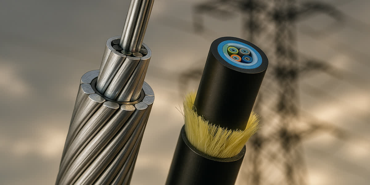
For substations fed by high-capacity overhead transmission lines using heavy ACSR conductor systems, fault current magnitudes can reach 40 kA to 50 kA. In such high-stress yards, peripheral conductor spacing must be tightly compressed (e.g., grading rings with $D = 2.5\,m$ near corner fence perimeters) to prevent fatal touch potential rises on boundary fences.
3. Galvanized Steel Wire (GSW) vs. Copper: Engineering Trade-Off Analysis
When designing a grounding grid, transmission utilities evaluate four core engineering vectors: electrical performance, theft vulnerability, galvanic interaction with civil foundations, and procurement lifecycle cost.
| Engineering Factor | Electrolytic Copper Earth Mat | Hot-Dip Galvanized Steel Wire Strand (GSW) | Engineering Verdict & Application Context |
|---|---|---|---|
| Electrical Conductivity | 100% IACS ($\rho = 1.72\,\mu\Omega\cdot cm$) | 9% - 11% IACS ($\rho = 18.0\,\mu\Omega\cdot cm$) | Copper requires smaller cross-section; GSW requires larger diameter but increases mechanical robustness. |
| Theft Vulnerability | Extremely High: Global black-market scrap copper value leads to widespread grid severance. | Virtually Zero: Steel scrap has negligible economic value, completely eliminating vandalism risk. | Decisive factor for remote substations, African/Latin American grids, and unfenced solar parks. |
| Galvanic Corrosion of Foundations | Aggressive: Copper is highly cathodic (+0.34 V vs SHE). It drives severe galvanic corrosion of nearby buried steel rebar and foundation piles. | Compatible: Zinc coating (-0.76 V) provides sacrificial cathodic protection to steel reinforced concrete piles and substation anchor rods. | GSW protects substation civil infrastructure; copper accelerates steel structural foundation degradation. |
| Soil Chemical Resilience | Excellent in neutral and acidic soils, but prone to rapid corrosion in soils with sulfides, ammonia, or organic acids. | Excellent in alkaline and neutral soils ($pH\,6.0 - 9.0$). ASTM A475 Class C zinc coating provides 40+ years of barrier protection. | GSW excels in arid, sandy, alkaline, and high-resistivity rocky terrain. |
| Mechanical Tensile Strength | Low ($200 - 250\,MPa$ annealed). Vulnerable to shear failure during heavy trench compaction or ground settlement. | High ($1300 - 1800\,MPa$ EHS grade). Resists heavy mechanical stress, backfill rock strikes, and seismic shifting. | GSW prevents mesh breakage during civil earthmoving and heavy machinery movement. |
| Total System Capex | High initial investment; volatile commodity pricing creates unpredictable EPC budget overruns. | Substantially lower ($40\% - 60\%$ material cost savings compared to equivalent copper ampacity). | GSW yields massive balance-of-plant capital efficiency for large-scale utility yards. |
4. Soil Resistivity Modeling & Ground Grid Resistance Optimization
The total resistance of the substation earth grid ($R_g$) directly dictates the Ground Potential Rise ($GPR = I_G \cdot R_g$), which governs electrical stress on outgoing telecommunication circuits, auxiliary controls, and cable screening.
4.1 Wenner Four-Pin Resistivity Profiling (IEEE Std 81)
Accurate earth grid design requires multi-depth soil resistivity profiling using the Wenner array: $$\rho_a = 2 \pi a R$$ Where $a$ is the equal spacing between the four collinear electrodes, and $R$ is the measured resistance ($V/I$). By varying pin spacing $a$ from $1.0\,m$ up to $30.0\,m$, engineers construct an apparent resistivity curve ($\rho_a$ vs. $a$) to establish a two-layer soil model consisting of top layer resistivity ($\rho_1$), top layer depth ($h$), and deep bedrock resistivity ($\rho_2$).
4.2 Sverak Formulation for Earth Grid Resistance
For a ground grid covering surface area $A$ with total buried conductor length $L_T$ at depth $h$, grid resistance $R_g$ is accurately approximated using Sverak's formula:
$$R_g = \rho \left[ \frac{1}{L_T} + \frac{1}{\sqrt{20 A}} \left(1 + \frac{1}{1 + h \sqrt{20/A}}\right) \right]$$
In compact substations where available land area $A$ is restricted, achieving $R_g < 1.0\,\Omega$ or $R_g < 0.5\,\Omega$ through horizontal conductors alone is mathematically impossible. Engineers must supplement the horizontal galvanized steel grid with deep-driven vertical earth rods (3m to 6m lengths) or drilling borehole grounding wells penetrating deep water tables.
Furthermore, inside cable trenches and control building conduits, outgoing underground cable systems and high-voltage medium-voltage power cables must have their metallic screens bonded and grounded to this master grid to eliminate circulating shield currents and prevent insulation punch-through during system switching transients.
5. Substation Grounding Hardware, Riser Terminations & Joint Integrity
A grounding grid is only as dependable as its underground joints and above-ground equipment riser terminations. A high-resistance connection point degrades under high fault current, creating localized arc flash, thermal fusing, and loss of safety continuity.
+----------------------------------------------------------------------------------------------------+
|                         SUBSTATION GROUNDING CONNECTION ARCHITECTURE                              |
+----------------------------------------------------------------------------------------------------+
|                                                                                                    |
|    EQUIPMENT GROUNDING RISER CONNECTION:                                                           |
|    [Transformer Neutral / Arrester Ground Terminal]                                                |
|                     |                                                                              |
|    [Heavy-Duty Compression Cable Lug (Bimetallic or Tinned Copper)]                                |
|    (Torque-controlled stainless steel hardware with Belleville disc spring washers)                |
|                     |                                                                              |
|    Heavy Galvanized Steel Wire Riser or Tinned Copper Flat Bar                                     |
|                     |                                                                              |
|    /////////////////|//////////////////////////////////////////////// Natural Grade Grade Level    |
|                     |                                                                              |
|    UNDERGROUND GRID JOINT (Buried 0.6m Depth):                                                     |
|                                                                                                    |
|    Option A: Exothermic Weld Connection                 Option B: Heavy Compression C-Wedge Clamp  |
|         (Molecular Alloy Bonding)                             (High-Pressure Mechanical Joint)     |
|              \     |     /                                          \     |     /                  |
|               \    |    /                                            \    |    /                   |
|        ========[#######]======== Main Grid Conductor          ========[=======]======== Main Grid  |
|                    |     (Galvanized Steel Strand)                        |                        |
|                    v                                                      v                        |
|             Branch Conductor                                       Branch Conductor                |
|                                                                                                    |
+----------------------------------------------------------------------------------------------------+
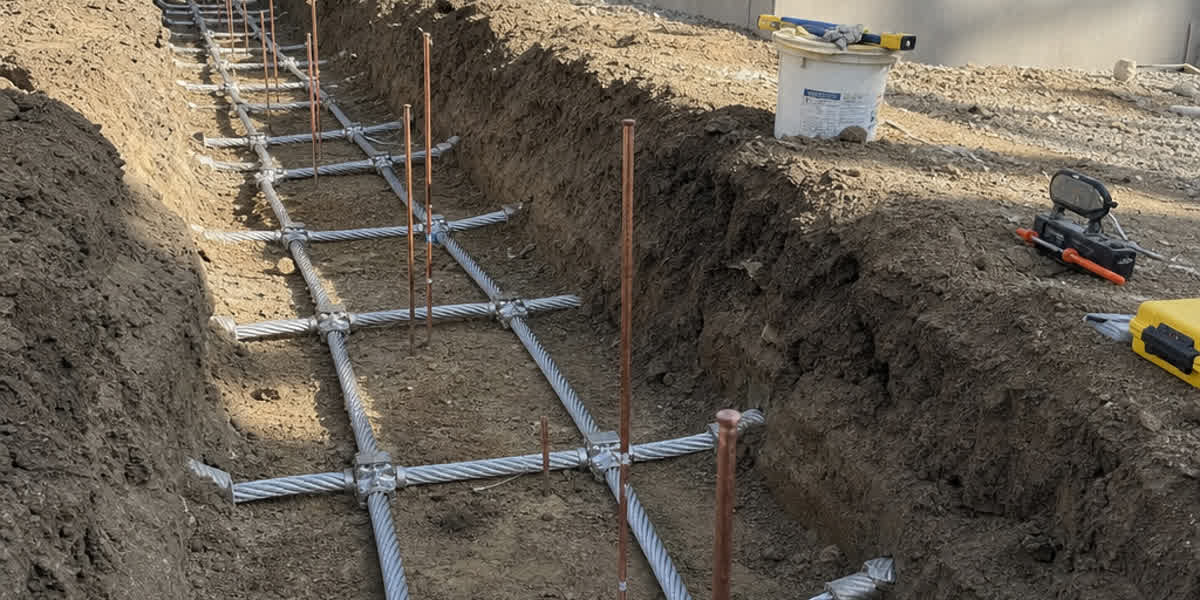
5.1 Underground Mesh Interconnections: Exothermic Welding vs. Compression Connectors
Buried grid conductor intersections (T-joints, cross-joints, and cable-to-ground-rod connections) must comply with IEEE Std 837 (Standard for Qualifying Permanent Connections Used in Substation Grounding): - Exothermic Welding: For galvanized steel strand grids, specialized high-temperature graphite molds and steel-specific weld powders form an iron-copper molecular alloy block. The weld completely encapsulates stripped wire ends, providing an uncrackable joint with zero air gaps or moisture ingress paths. - Heavy Compression C-Wedge & Parallel Clamps: Engineered from ductile high-conductivity copper or forged steel, hydraulic compression tools (delivering 12 to 14 tons of force) cold-weld the strands together, ensuring gas-tight electrical contact without requiring open-flame ignition powders in hazardous industrial atmospheres.
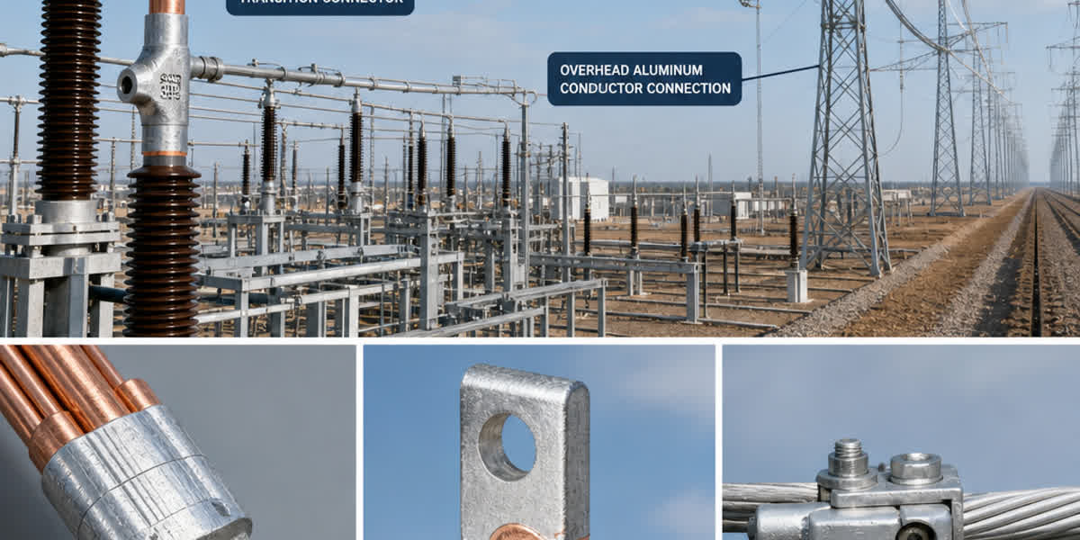
5.2 Equipment Riser Terminations & Bimetallic Transitions
Above ground, grounding leads transition from the buried grid to connect electrical apparatus: 1. Transformer Neutrals & Surge Arresters: Must be connected to the grid with two independent paths using heavy-duty cable lugs and bimetallic terminals to guarantee fault clearing even if one conductor suffers physical severance. 2. Structural Steel Gantries & Switchgear Frames: Connected via overhead line fittings & hardware including heavy-duty grounding clamps, serrated Belleville spring washers to maintain constant contact pressure under cyclic thermal expansion, and antioxidant joint compounds (petroleum-based grease with suspended zinc particles) to prevent moisture ingress.
6. Manufacturing Excellence & Technical Specifications at SiTong Cable
As a premier power cable and overhead conductor manufacturer, Zhengzhou SiTong Cable Co., Ltd. (SiTong Cable) engineers and supplies high-performance hot-dip galvanized steel wire strands and substation grounding systems engineered to meet ASTM A475, ASTM A363, BS 183, IEC 60888, and AS 1222 standards.
6.1 Heavy Hot-Dip Galvanizing & Metallurgical Quality Control
To ensure maximum corrosion endurance in aggressive subterranean soils, SiTong Cable implements strict metallurgical and quality-assurance controls: - High-Carbon Steel Raw Materials: High-purity wire rods (Grades 65, 70, and 72) subjected to continuous patenting heat treatment, ensuring uniform sorbite microstructure with superior tensile elasticity and torsion resistance. - Triple-Galvanizing Bath Technology: Continuous in-line hot-dip galvanizing lines applying ultra-pure zinc (minimum 99.995% purity per ASTM B6). Coating thicknesses are calibrated to exceed ASTM A475 Class A ($245\,g/m^2$), Class B ($490\,g/m^2$), and Class C ($735\,g/m^2$) criteria for extreme alkaline or coastal marine environments. - Zero-Porosity Interfacial Alloy Layer: Precise temperature-controlled zinc kettles generate a uniform, ductile iron-zinc alloy layer that prevents flaking, cracking, or zinc spalling during high-stress twisting and mechanical strand installation.
6.2 Standard Technical Parameters for SiTong Galvanized Steel Wire Strand (ASTM A475)
| Nominal Diameter ($mm$) | Construction (Wires / Wire $\phi$) | Steel Grade Designation | Min. Breaking Strength ($kN$) | Approx. Weight ($kg/km$) | Zinc Coating Class A ($g/m^2$) | Zinc Coating Class C ($g/m^2$) |
|---|---|---|---|---|---|---|
| 9.53 mm (3/8") | 7 / 3.05 mm | Extra High Strength (EHS) | 68.5 kN | 407 kg/km | 260 g/m² | 760 g/m² |
| 11.11 mm (7/16") | 7 / 3.68 mm | Extra High Strength (EHS) | 92.5 kN | 595 kg/km | 275 g/m² | 800 g/m² |
| 12.70 mm (1/2") | 7 / 4.19 mm | Extra High Strength (EHS) | 120.1 kN | 772 kg/km | 290 g/m² | 850 g/m² |
| 15.24 mm (0.60") | 19 / 3.05 mm | High Strength (HS) | 148.0 kN | 1105 kg/km | 260 g/m² | 760 g/m² |
| 18.00 mm (0.71") | 19 / 3.60 mm | High Strength (HS) | 205.0 kN | 1540 kg/km | 275 g/m² | 800 g/m² |
Every production reel undergoes comprehensive destructive and non-destructive laboratory testing in SiTong’s CNAS-aligned testing facility, including: 1. Preece Copper Sulfate Dip Testing (verifying zinc coating uniformity without iron breakthroughs). 2. Wire torsion and elongation testing per ASTM A475 Clause 13. 3. Electrical DC resistance measurement to calibrate fault-energy thermal ratings. 4. Salt-spray corrosion chamber testing (ASTM B117) exceeding 1000 hours of continuous exposure.
7. Frequently Asked Questions (FAQ)
Q1: Why are power utilities replacing copper substation earth grids with galvanized steel wire strands?
Utilities are transitioning to hot-dip galvanized steel wire strands primarily due to zero theft vulnerability and foundation compatibility. Scrap-copper theft from unmanned substations has caused catastrophic utility accidents, severe outages, and personnel fatalities when equipment loses grounding continuity. Steel scrap has negligible commercial salvage value, eliminating vandalism. Furthermore, buried copper drives severe galvanic corrosion of adjacent steel reinforced concrete foundations, whereas galvanized steel has a compatible electrochemical potential that preserves civil assets.
Q2: How does the higher electrical resistance of steel affect substation safety compared to copper?
Although steel has approximately 9% to 11% of copper's electrical conductivity, the total resistance of a substation grounding grid ($R_g$) is dominated by the soil resistivity and the physical geometric footprint of the mesh, not the internal resistance of the conductor metal. Conductor resistance accounts for less than 1% to 2% of total substation grounding impedance. By increasing the steel strand cross-sectional area to satisfy IEEE Std 80 thermal limits ($I^2 t$), a galvanized steel earth grid achieves identical touch and step voltage safety margins as a copper grid.
Q3: What is the purpose of the crushed rock gravel layer placed on substation yard surfaces?
The crushed rock layer (typically 100 mm to 150 mm of washed granite or limestone with a resistivity $\rho_s \ge 3000\,\Omega\cdot m$) acts as a critical high-resistance series buffer between the human feet and the lower-resistivity underlying soil. As modeled in IEEE Std 80, this high-resistivity surface buffer drastically increases the permissible touch voltage threshold (from ~250 V on bare moist soil up to ~850 V with gravel) and step voltage threshold (up to >2600 V), preventing ventricular fibrillation during phase-to-ground faults.
Q4: Which zinc coating class should be specified for subterranean galvanized steel ground grids?
For underground grounding meshes, ASTM A475 Class B or Class C (with minimum zinc weights of $490\,g/m^2$ to $735\,g/m^2$) is strongly recommended over standard Class A. In subterranean soils with neutral to alkaline pH ($6.0 \le pH \le 8.5$) and resistivity above $30\,\Omega\cdot m$, Class C heavy galvanization delivers between 35 and 50 years of sacrificial cathodic protection before the underlying high-carbon steel strand experiences structural corrosion.
Q5: How are equipment riser leads bonded between galvanized steel grids and copper equipment terminals?
When connecting galvanized steel grounding risers to copper apparatus terminals (such as transformer grounding pads or busbar disconnects), engineers must use tinned copper or bimetallic compression cable lugs and torque-controlled stainless steel hardware. In humid or coastal atmospheres, direct contact between bare copper and zinc-coated steel triggers rapid galvanic corrosion of the zinc layer. Bimetallic transitions, tinned coatings, and non-conductive weatherproofing mastic tape completely insulate the joint against moisture and galvanic degradation.
8. Engineering Summary & Procurement Checklist
Designing a reliable, cost-effective substation grounding grid requires a balanced synthesis of electromagnetic modeling, metallurgical resilience, and life-cycle economics: 1. Conduct precision multi-depth soil resistivity surveys using the Wenner array to identify true two-layer earth structures. 2. Calculate ground grid conductor cross-sections under IEEE Std 80 formulas using conservative fault clearance durations ($t_c \ge 0.5\,s$). 3. Eliminate substation theft vulnerability and protect civil concrete foundations by evaluating high-strength galvanized steel wire strands for the buried perimeter and interior meshes. 4. Ensure all underground joints utilize certified exothermic welds or heavy hydraulic compression clamps complying with IEEE Std 837. 5. Apply heavy ASTM A475 Class C zinc coatings for long-term corrosion survivability in aggressive soils.
👉 Explore SiTong Cable's high-strength galvanized steel wire strand range
👉 Review our ACSR conductor specifications for substation gantry busbars
👉 Contact our engineering and technical support team for custom substation grounding grid design
📬 Sales inquiries: sales@sitongcable.com | 📞 Phone: +86-371-69176007