OPGW vs. ADSS Cable for Overhead Transmission Lines: Space Potential, Induced Voltage, Dry-Band Arcing & Structural Selection Guide
OPGW vs. ADSS Cable for Overhead Transmission Lines: Space Potential, Induced Voltage, Dry-Band Arcing & Structural Selection Guide
High-voltage transmission line engineers evaluating OPGW vs. ADSS cables must balance space potential, dry-band arcing, short-circuit current, and tower structural loading across 35kV to 500kV grids.
Selecting the optimal optical telecommunication and grid-monitoring cable for high-voltage (HV) and extra-high-voltage (EHV) overhead power lines is one of the most consequential decisions in transmission line design and network modernization. Electrical utilities, EPC contractors, and telecommunications network operators face a fundamental technical fork: should optical infrastructure be integrated directly into the overhead ground wire as Optical Ground Wire (OPGW) at the tower apex, or deployed as an All-Dielectric Self-Supporting (ADSS) cable underbuilt beneath or within the energized phase conductor bundle?
While both cable architectures leverage low-loss single-mode optical fibers compliant with ITU-T G.652.D or G.655 for supervisory control and data acquisition (SCADA), line differential protection, and commercial broadband transit, their electrical physics, mechanical loading dynamics, and lifecycle operational limits diverge radically. This technical guide delivers an in-depth, physics-based comparative analysis of OPGW and ADSS cables in accordance with IEEE 1138, IEEE 1222, IEC 60794-4-10, and CIGRE Technical Brochure 340.
1. Structural Architecture & Material Physics
The fundamental operational distinction between OPGW and ADSS stems from their material chemistry and conductive properties.
+-------------------------------------------------------------------------------+
|                        OPGW vs. ADSS CROSS-SECTION                            |
+-------------------------------------------------------------------------------+
|                                                                               |
|            OPGW (Metallic & Conductive)              ADSS (All-Dielectric)    |
|                                                                               |
|             /-------------------------\            /-------------------------\|
|            |     Outer ACS Strands     |          |     Outer PE / TR Jacket  ||
|            |   /---------------------\ |          |   /---------------------\ ||
|            |  |  Inner AA / ACS Wire  ||          |  |  Aramid Yarn Layer    |||
|            |  |   /----------------\  ||          |  |   /----------------\  |||
|            |  |  |  Laser-Welded    | ||          |  |  |  Inner PE Jacket | |||
|            |  |  |  Stainless Steel | ||          |  |  |   /------------\ | |||
|            |  |  |  Optical Tube    | ||          |  |  |  | Loose Tubes  || |||
|            |  |  |   [Fibers + Gel] | ||          |  |  |  | Around FRP   || |||
|            |  |   \----------------/  ||          |  |  |   \------------/ | |||
|            |   \---------------------/ |          |   \---------------------/ ||
|             \-------------------------/            \-------------------------/|
+-------------------------------------------------------------------------------+
Optical Ground Wire (OPGW) Architecture
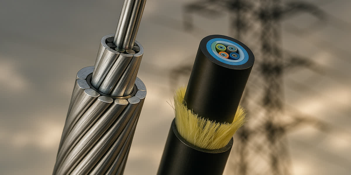
OPGW is fundamentally a hybrid electro-mechanical-optical conductor. At its mechanical core resides one or more hermetically sealed, central or stranded stainless steel tubes (SUS 304 or SUS 316L) filled with hydrogen-scavenging, thixotropic water-blocking gel enclosing 12 to 144 optical fibers. Surrounding this optical core are concentric layers of high-tensile metallic wires: - Aluminum-Clad Steel (ACS) Wires (ASTM B415 / IEC 61232): Provide primary tensile strength, lightning arc resistance, and high mechanical modulus ($E \approx 160\text{ GPa}$). - Aluminum Alloy Wires (AA) (ASTM B398 / EN 50183): Deliver electrical conductivity ($52.5\%\text{ to }53\%\text{ IACS}$) required to conduct system fault currents safely to earth without excessive $I^2t$ joule heating.
In existing transmission infrastructure, OPGW directly replaces legacy shielding lines such as traditional galvanized steel wire strand or aluminum-clad steel shield wires at the tower peak.
All-Dielectric Self-Supporting (ADSS) Architecture
ADSS contains zero metallic elements, rendering it electrically non-conductive. Its architecture consists of: - Central Strength Member (CSM): Non-metallic Fiber Reinforced Polymer (FRP) rod, providing axial anti-buckling stiffness. - Optical Core: Stranded PBT (Polybutylene Terephthalate) loose buffer tubes stranded around the FRP in an SZ configuration, filled with water-blocking gel and dry swellable yarns. - Tensile Reinforcement Layer: Stranded high-modulus aramid yarns (Kevlar® / Twaron®) that absorb $100\%$ of longitudinal tensile forces, yielding a light weight-to-strength ratio. - Protective Outer Jacket: High-density polyethylene (HDPE) for low-voltage environments, or specialty tracking-resistant cross-linked polymer (TR jacket) for high electric fields.
2. Electromagnetic Field Physics: Space Potential ($V_s$) & Dry-Band Arcing
The single greatest operational hazard for ADSS cables installed on high-voltage transmission lines is dry-band electrical tracking and erosion, governed by capacitive induction from adjacent high-voltage phase conductors.
+-------------------------------------------------------------------------------+
|                       DRY-BAND ARCING PHENOMENON ON ADSS                      |
+-------------------------------------------------------------------------------+
|                                                                               |
|  Phase Conductor (e.g. ACSR)                                                  |
|        ( ~~~ High Voltage AC Field ~~~ )                                      |
|                       |                                                       |
|                       v Capacitive Coupling (C_line)                          |
|  ADSS Cable -------------------------------------------------------------     |
|             [ Polluted Wet Layer ] [ Dry Band Gap ] [ Polluted Wet Layer ]    |
|                      |                     ^                     |            |
|                      |               Concentrated                |            |
|                      |              Electric Field               |            |
|                      |              ( > 1.0 kV/cm )              |            |
|                      \==== Micro-Arcing Flashover ===============/            |
|                              (Carbonizes TR Sheath)                           |
|                       |                                                       |
|                       v Capacitive Coupling (C_ground)                        |
|  Tower Structure / Earth                                                      |
+-------------------------------------------------------------------------------+
The Space Potential Equation
When an ungrounded dielectric cable passes through the multi-phase electromagnetic field generated by energized ACSR conductor or AAAC conductor lines, a non-zero potential is induced along the cable jacket. The space potential $V_s$ at coordinate $(x, y)$ on the tower structure is calculated via electrostatic capacitance matrices:
$$V_s(x, y) = \sum_{j=1}^{m} \frac{C_{cj}(x, y)}{C_{total}(x, y)} V_j$$
Where: - $V_j$ is the complex phase-to-ground voltage of conductor $j$. - $C_{cj}$ is the mutual capacitive coupling between phase conductor $j$ and the ADSS cable location. - $C_{total}$ is the total capacitance of the ADSS cable to all phases and grounded tower bodies.
Dry-Band Arcing Degradation Mechanism
Under moist environmental conditions (fog, light drizzle, coastal salt spray, or industrial airborne pollution): 1. A thin film of conductive electrolyte coats the outer polyethylene jacket of the ADSS cable. 2. The induced longitudinal voltage drives a continuous capacitive leakage current ($I_{leak} \approx 0.5\text{ to }5\text{ mA}$) through the surface contamination layer toward grounded metallic tower suspension clamps. 3. Localized $I^2 R$ joule heating evaporates moisture faster than ambient replenishment, creating localized dry annular bands of high electrical resistance. 4. The entire induced potential difference across the span concentrates across this tiny millimeter-wide dry band, generating localized electric field gradients exceeding $1.0\text{ to }1.5\text{ kV/cm}$ (air breakdown voltage). 5. Scintillating electrical micro-arcs ignite across the dry band, generating surface temperatures exceeding $1,000^\circ\text{C}$. In standard HDPE jackets, these persistent sparks carbonize the polymer into conductive carbon tracks, eventually eroding through the jacket, degrading aramid load-bearing yarns, and causing catastrophic mechanical tensile drop.
Jacket Selection Thresholds According to IEEE 1222 & IEC 60794-4-20
| Nominal Line Voltage ($U_n$) | Calculated Space Potential ($V_s$) | Required ADSS Outer Jacket | Mitigation & Hardware Measures |
|---|---|---|---|
| $< 35\text{ kV}$ | $< 12\text{ kV}$ | Standard Black HDPE | Standard dielectric clamps; no corona rings required. |
| $66\text{ kV} - 132\text{ kV}$ | $12\text{ kV} \le V_s \le 25\text{ kV}$ | Tracking Resistant (TR) Jacket | Anti-tracking compound; Corona suppression rings installed at suspension points. |
| $> 220\text{ kV} - 500\text{ kV}$ | $> 25\text{ kV}$ | Not Recommended for ADSS | Space potential exceeds safe polymer limits; Mandatory use of OPGW. |
In contrast, our precision-engineered OPGW cable range is inherently immune to dry-band arcing and space potential damage. Because OPGW is solidly bonded to tower steel at every structure via metallic grounding leads, its outer metallic strands sit permanently at earth potential ($0\text{ V}$), entirely eliminating sheath breakdown.
3. Short-Circuit Thermal Capacity & Lightning Interception
Overhead power lines are subject to severe atmospheric lightning discharges and transient phase-to-earth fault currents.
+-------------------------------------------------------------------------------+
|                      LIGHTNING & FAULT RESISTANCE COMPARISON                  |
+-------------------------------------------------------------------------------+
|                                                                               |
|   EVENT                 OPGW BEHAVIOR                  ADSS BEHAVIOR          |
|  ---------------------------------------------------------------------------- |
|   Direct Lightning      ACS strands dissipate          Catastrophic burn-     |
|   Strike (100-200kA)    100-200 C charge. Core         through of polymer     |
|                         fibers remain < 180°C.         and severed fibers.    |
|                                                                               |
|   Single-Phase Ground   Carries symmetric fault        Zero fault current     |
|   Fault (10-40kA)       current to earth grid via      conduction; induced    |
|                         high-conductivity AA wires.    potential creates arcs.|
+-------------------------------------------------------------------------------+
OPGW Thermal Rating ($I^2 t$ Adiabatic Withstand)
During a single-phase-to-ground fault, fault currents ranging from $10\text{ kA}$ to $40\text{ kA}$ flow through the shielding system for $0.1$ to $0.5$ seconds. The thermal rating of OPGW is calculated using the adiabatic short-circuit energy formula from IEC 60949:
$$I_{sc} = \frac{K \cdot A}{\sqrt{t}} \sqrt{\ln\left(\frac{T_{max} + \beta}{T_0 + \beta}\right)}$$
Where: - $I_{sc}$ is the permissible short-circuit current ($\text{kA}$). - $A$ is the total cross-sectional area of the metallic strands ($\text{mm}^2$). - $T_0$ is the initial steady-state operating temperature (typically $40^\circ\text{C}$). - $T_{max}$ is the maximum permissible optical core temperature ($180^\circ\text{C}$ to $200^\circ\text{C}$ to preserve buffering gel and fiber coatings). - $K$ and $\beta$ are material constants for aluminum-clad steel and aluminum alloy.
SiTong Cable engineers design customized strand ratios of high-strength ACS and high-conductivity AA wires to achieve required short-circuit ratings (e.g., $50\text{ kA}^2\text{s}$ to $180\text{ kA}^2\text{s}$) tailored to regional substation fault clearing times.
Lightning Arc Resistance (Class 1 vs. Class 2 per IEC 60794-4-10)
OPGW sits at the pinnacle of transmission towers, acting as the primary lightning shield for energized phase conductors below. When intercepted by a lightning stroke (transferring $100\text{ to }200\text{ Coulombs}$ of electric charge), the outer metallic strands absorb the localized melting arc: - Aluminum-Clad Steel (ACS) strands exhibit a high melting point ($> 1,400^\circ\text{C}$ for steel core, $> 660^\circ\text{C}$ for aluminum cladding), resisting severe strand severing. - Pure Aluminum Alloy strands melt more rapidly under high charge transfer. Therefore, utility-grade OPGW specifies thick outer ACS wire layers ($> 2.8\text{ mm}$ to $3.5\text{ mm}$ diameter).
ADSS has zero lightning interception capability. If lightning directly strikes an ADSS cable—which can occur under shielding angle failures on lines with wide crossarms—the intense plasma arc instantly vaporizes the outer jacket, incinerates the aramid yarns, and shatters the optical fibers.
4. Mechanical & Civil Tower Engineering: Sag-Tension and Wind/Ice Loads
Installing an optical cable introduces structural forces that directly impact the civil safety factors of transmission towers and wooden/concrete poles.
+-------------------------------------------------------------------------------+
|                       TOWER STRUCTURAL IMPACT PROFILE                         |
+-------------------------------------------------------------------------------+
|                                                                               |
|   OPGW ON TOWER APEX:                             ADSS UNDERBUILT ON TOWER:   |
|   - Replaces existing ground wire.               - Added new physical cable.  |
|   - Zero incremental wind/ice load.              - Adds transverse wind drag. |
|   - Zero eccentric torsional moment.             - Adds eccentric torque to   |
|   - Preserves ground clearance profile.            tower body and crossarms.  |
|                                                  - Consumes ground clearance. |
|                 / \                                            / \            |
|                /   \ <-- OPGW at Apex                         /   \           |
|               /-----\                                        /-----\          |
|              / |   | \                                      / |   | \         |
|         ----/--|---|--\---- Phase Conductor            ----/--|---|--\----    |
|                |   |                                          |   |           |
|                |   |                                          |   | <-- ADSS  |
|                |   |                                          |   |           |
|               /     \                                        /     \          |
+-------------------------------------------------------------------------------+
1. Structural Tower Loading: Zero-Sum vs. Added Penalty
- OPGW (1-to-1 Replacement): On existing transmission lines, OPGW is installed as a direct physical replacement for an aging galvanized steel or Alumoweld earth wire. Because the outer diameter and unit weight of OPGW closely match legacy shield wires, no net transverse wind load, radial ice weight, or overturning moment is added to the tower foundations.
- ADSS (Additive Load Penalty): ADSS represents an entirely new physical span suspended on the tower body or crossarms. Under heavy wind ($> 120\text{ km/h}$) and radial ice loading ($10\text{ to }20\text{ mm}$ glaze ice), ADSS introduces substantial transverse shear forces and an eccentric torsional twisting moment onto the tower lattice. For older lattice towers or wooden distribution poles, this frequently requires expensive structural steel reinforcement or pole replacement.
2. Ground and Mid-Span Clearance Constraints
ADSS must be installed beneath the phase conductors to minimize space potential. However, this positioning forces the ADSS cable into the lowest clearance envelope of the right-of-way (ROW): - The maximum sag of ADSS under summer high-ambient operating conditions ($40^\circ\text{C}$ to $50^\circ\text{C}$) must maintain statutory clearances over road crossings, railways, and vegetation. - Under winter ice-shedding conditions, phase conductors can gallop or shed ice asynchronously, creating severe vertical phase-to-ADSS clash hazards.
3. Vibration Protection & Hardware Systems
Both OPGW and ADSS cables are vulnerable to high-frequency, low-amplitude aeolian vibration ($10\text{ to }50\text{ Hz}$) induced by laminar winds ($1\text{ to }7\text{ m/s}$), which causes bending fatigue at support clamps: - OPGW Hardware: Utilizes cast aluminum suspension clamps lined with preformed neoprene cushions and helical armour rods, paired with multi-frequency asymmetrical Stockbridge vibration dampers. - ADSS Hardware: Requires non-metallic or dielectric-insulated preformed dead-end grips and specialized overhead line fittings and hardware designed to distribute radial clamping pressure over large surface areas to prevent crushing the internal PBT buffer tubes. Spiral vibration dampers (SVD) are installed on smaller ADSS spans.
5. Comprehensive Comparison Matrix: OPGW vs. ADSS
The following technical comparison matrix provides transmission system planners with a direct reference for specification trade-offs:
| Engineering Parameter | Optical Ground Wire (OPGW) | All-Dielectric Self-Supporting (ADSS) |
|---|---|---|
| Governing Standards | IEEE 1138, IEC 60794-4-10 | IEEE 1222, IEC 60794-4-20 |
| Applicable Line Voltage | $35\text{ kV}$ to $1,000\text{ kV}$ (Universal) | Sub-distribution to $132\text{ kV}$ ($220\text{ kV}$ with TR jacket) |
| Installation Location | Tower Peak / Peak Crossarm (Earth wire position) | Tower Body or Lower Crossarm (Underbuilt) |
| Conductive Nature | Fully Metallic / Conductive (ACS + AA wires) | $100\%$ Non-Metallic / All-Dielectric |
| Lightning Interception | Primary Shield ($100 - 200\text{ C}$ rating, Class 1/2) | Zero capability (Destructive failure if struck) |
| Short-Circuit Fault Current | High Capacity ($10 - 40\text{ kA}$, up to $200\text{ kA}^2\text{s}$) | Zero (Cannot conduct or ground fault currents) |
| Space Potential Vulnerability | Immune (Continuously bonded to earth grid) | Severe Risk (Dry-band arcing if $V_s > 12\text{ kV}$) |
| Tower Civil Load Impact | Neutral (Replaces existing ground wire) | Additive (Increases wind, ice, and torsional loads) |
| Live-Line Installation | Difficult (Requires line outage or safety clearances) | Excellent (Can be installed with lines energized) |
| Shotgun & Rodent Resistance | Maximum (Armoured metallic outer layer) | Low (Susceptible to hunters, rodents, birds) |
| Design Life Expectancy | $30 - 40\text{ Years}$ | $20 - 25\text{ Years}$ (Polymer aging / UV degradation) |
| Relative Material Cost | Moderate to High | Low to Moderate |
| Total Project CAPEX | Optimal for new builds & reconductoring | Optimal for live-line retrofit telecommunications |
6. Substation Gantry Transition & Underground Termination
At transmission line terminal structures, optical communications must transition from overhead exposure into the substation control room or telecom rack:
Overhead Line (OPGW / ADSS)
       │
       ▼
[ Tower-Mounted Splice Box (IP68) ] ── (Grounding Lead to Earth Bus)
       │
       ▼ Non-Metallic Dielectric Downlead Cable / Armoured Underground Fiber
       │ (Secured by Stainless Steel Clamps every 1.5m)
       │
[ Substation Cable Trench / Duct Bank ]
       │
       ▼
[ Control Building ODF / Telecom Rack ]
- Downlead Clamping: OPGW is clamped to the tower leg using rubber-cushioned downlead clamps every $1.5\text{ to }2.0\text{ meters}$ to prevent wind slap against steel bracing.
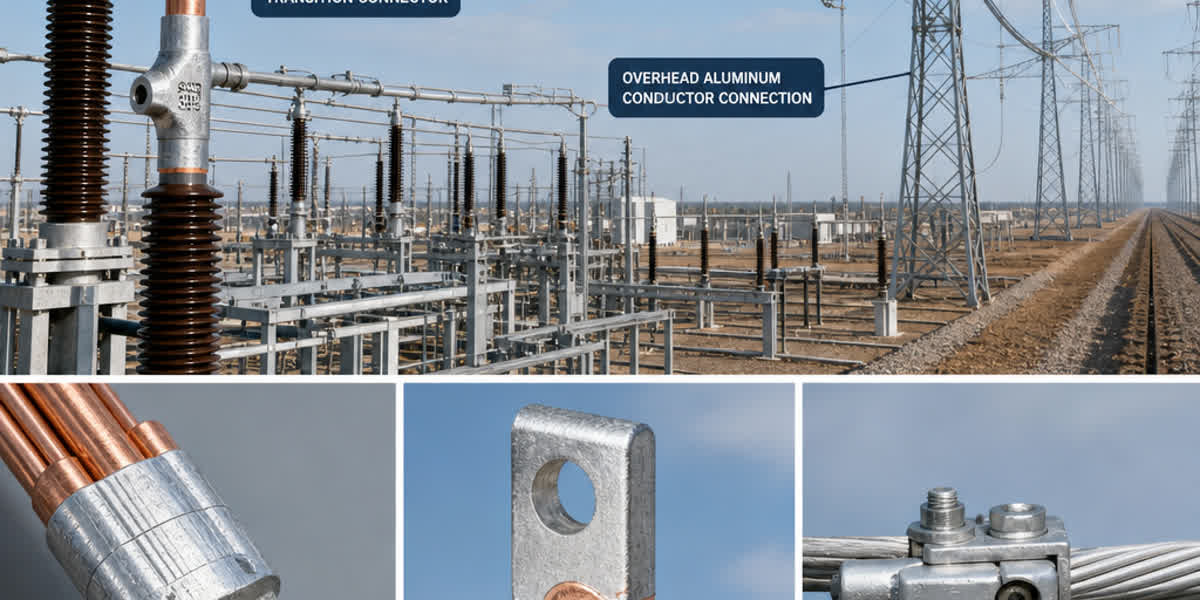
- Metallic Sheath Earthing: At terminal gantries, the metallic outer sheath of the OPGW must be grounded to the substation earth mat using bimetallic grounding straps and heavy-duty terminal hardware to drain induced currents safely before entering the splice enclosure.
- Transition to Underground Infrastructure: Within the substation boundary, optical cables enter underground duct systems alongside medium-voltage auxiliary power and underground cable networks, requiring dielectric, rodent-proof breakout cables to prevent ground potential rise (GPR) transfer into the control room.
7. Manufacturing Quality Assurance & Standards Compliance
Zhengzhou Sitong Cable Co., Ltd. (SiTong Cable / 郑州四通电缆) operates specialized, automated manufacturing lines dedicated to overhead transmission and fiber optic infrastructure:
- Laser-Welded Stainless Steel Tubes: Fabricated with continuous optical fiber excess length (EFL) control, ensuring zero strain on single-mode fibers under maximum design tension (MDT).
- Automated Planetary Stranding: Uniform wire back-tension during ACS and aluminum alloy stranding minimizes residual internal mechanical stresses, preventing loose strands during tension stringing.
- Full Type-Testing Validation: All cables undergo full mechanical and optical type testing compliant with IEEE 1138, IEEE 1222, and IEC 60794-4, including:
- Sheave test (stringing wheel simulation)
- Aeolian vibration test (100 million cycles)
- Galloping and short-circuit thermal impulse testing
- Water penetration and temperature cycling ($-40^\circ\text{C}$ to $+70^\circ\text{C}$)
8. Frequently Asked Questions (FAQ)
Q1: When should an engineer choose OPGW over ADSS?
A: OPGW is the preferred choice for all new high-voltage transmission lines ($66\text{ kV}$ to $500\text{ kV}+$), full-line reconductoring projects, and lines where existing shield wires (such as galvanized steel strand) have reached end-of-life. It provides combined lightning protection, heavy fault current dissipation, zero dry-band arcing vulnerability, and a 40-year service life without consuming additional tower attachment space.
Q2: When is ADSS the more economical and practical choice?
A: ADSS is ideal for: 1. Retrofitting fiber optic communication onto existing, energized transmission lines without scheduling costly grid outages (live-line stringing below phase conductors). 2. Medium-voltage rural distribution networks ($11\text{ kV}$ to $33\text{ kV}$) supported on wooden or concrete poles where space potential is well below $12\text{ kV}$. 3. Telecom utility overbuilds where the utility leases tower space to third-party telecommunication providers without modifying the primary power conductors.
Q3: What is the primary cause of ADSS cable failure on 220kV lines?
A: The primary failure mode is dry-band electrical tracking. On $220\text{ kV}$ circuits, the induced space potential frequently exceeds $20\text{ to }25\text{ kV}$. Under polluted or wet ambient conditions, high leakage currents create dry bands where micro-arcing incinerates the outer jacket and carbonizes the aramid load-bearing yarns, resulting in tensile breakage. Installing tracking-resistant (TR) jackets and positioning the cable strictly within low-potential field coordinates (calculated via finite element electrostatics) are mandatory.
Q4: Does OPGW add more ice and wind weight to the tower than ADSS?
A: No. OPGW replaces an existing overhead ground wire of comparable physical diameter and mass, resulting in zero net increase in structural tower loading. Conversely, ADSS adds a completely new mechanical span, introducing additional transverse wind profile, radial ice accumulation, and eccentric torsional moments on the tower structure.
9. Conclusion & Engineering Support
Balancing structural civil loads, space potential induction, lightning interception, and live-line construction determines whether OPGW or ADSS delivers the lowest total cost of ownership (TCO) for your grid network.
👉 Browse our complete OPGW cable range
👉 Read our OPGW Installation & Maintenance Field Guide
👉 Contact our engineering team for space potential calculations & custom OPGW design
📬 Sales & Technical Inquiries: sales@sitongcable.com | 📞 Direct Line: +86-371-69176007