Overhead Line Icing & Conductor Galloping Mitigation: Heavy Ice-Loading Sizing, High-Tensile ACSR, TDD Dampers & Sag-Tension Engineering
Overhead Line Icing & Conductor Galloping Mitigation: Heavy Ice-Loading Sizing, High-Tensile ACSR, TDD Dampers & Sag-Tension Engineering
Atmospheric icing and wind-induced conductor galloping present severe structural hazards to overhead transmission lines in cold and mountainous climates. This engineering guide examines ice accretion mechanisms, radial ice load calculations under IEC 60826 and ASCE 74, conductor selection criteria comparing high-strength steel-core ACSR with AAAC, dynamic ice-shedding jump dynamics, and proven hardware countermeasures including torsional damper detuners (TDD) and interphase spacers.
1. Introduction: Atmospheric Icing Physics and Structural Hazards
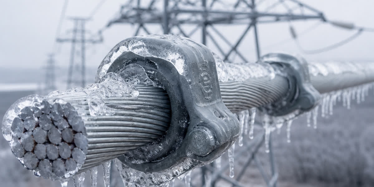
Overhead transmission and distribution lines traversing alpine corridors, high-latitude territories, and river-valley wind gaps frequently encounter extreme meteorological freezing events. When supercooled atmospheric droplets impinge upon overhead conductors at ambient temperatures between -10°C and 0°C, ice accretion begins. The historical consequences of unmitigated conductor icing are catastrophic: catastrophic tower crossarm collapses, tensile failure of conductor strands, asymmetric ice-shedding flashovers, and high-energy conductor galloping (low-frequency, high-amplitude aeroelastic instability).
Power utilities designing overhead transmission networks must account for three distinct physical categories of atmospheric icing, each exhibiting unique mass densities, adhesion strengths, and aerodynamic profiles:
- Glaze Ice (Freezing Rain / 雨凇): Formed when liquid raindrops freeze immediately upon impacting cold conductor surfaces (typically -3°C to 0°C). Glaze ice features a high density of approximately $0.90\text{ g/cm}^3$, high optical transparency, and exceptional mechanical adhesion shear strength (>0.5 MPa). It creates massive vertical gravitational overload and forms smooth, teardrop or crescent-shaped aerodynamic cross-sections susceptible to galloping.
- Hard Rime (In-Cloud Freezing Fog / 硬雾凇): Generated by the continuous impingement of supercooled fog droplets in moderate-to-high winds at temperatures between -8°C and -2°C. With a density of $0.60\text{ to }0.85\text{ g/cm}^3$, hard rime exhibits an opaque, milky crystalline structure that grows into the windward side of the conductor, generating severe aerodynamic eccentricity and rotational torque.
- Wet Snow (湿雪): Occurs at temperatures slightly above freezing (+0.5°C to +2.0°C) when partially melted snow crystals collide with the conductor. With moisture content between 15% and 40%, wet snow compresses around the conductor under torsional rotation, forming cylindrical sleeves with densities varying from $0.20\text{ to }0.60\text{ g/cm}^3$, creating substantial static sag.
| Atmospheric Icing Type | Typical Formation Temp (°C) | Mass Density ($\text{g/cm}^3$) | Adhesion to Conductor | Aerodynamic Cross-Section | Primary Failure Mode |
|---|---|---|---|---|---|
| Glaze Ice | -3 to 0 | 0.85 – 0.92 | Extremely High (>0.5 MPa) | Crescent / Teardrop | Static mechanical overload & violent galloping |
| Hard Rime | -8 to -2 | 0.60 – 0.85 | High (0.2 – 0.5 MPa) | Asymmetric Windward Wedge | Torsional rotation & aerodynamic flutter |
| Soft Rime | <-8 | 0.15 – 0.40 | Low (<0.1 MPa) | Granular / Feathery | Minor load, low structural risk |
| Wet Snow | 0 to +2 | 0.20 – 0.60 | Moderate (Cohesive) | Cylindrical Sleeve | High static sag & ground clearance loss |
Understanding the physical properties of these deposits allows transmission line design engineers to apply appropriate international structural codes, notably IEC 60826 (Design criteria of overhead transmission lines), CIGRE Technical Brochure 322 (State of the Art of Conductor Galloping), and ASCE Manual of Practice No. 74 (Guidelines for Electrical Transmission Line Structural Loading).
2. Mechanical Load Calculations & Sag-Tension Analysis Under Radial Ice
Radial ice accretion exerts a simultaneous double penalty on overhead conductors: it exponentially multiplies the dead weight per unit length and expands the projected frontal area exposed to transverse wind pressure. Under IEC 60826, the total resultant unit design load $w_r$ (expressed in $\text{N/m}$) combining conductor bare weight, ice sleeve weight, and transverse wind force is modeled as:
$$w_r = \sqrt{(w_c + w_i)^2 + w_w^2}$$
Where: - $w_c$ is the bare conductor self-weight ($\text{N/m}$). - $w_i = \pi \cdot g \cdot \rho_i \cdot b \cdot (d_c + b)$ is the radial ice weight per meter, where $b$ is the radial ice thickness ($\text{m}$), $d_c$ is the bare conductor outside diameter ($\text{m}$), $\rho_i$ is ice density ($\text{kg/m}^3$), and $g = 9.807\text{ m/s}^2$. - $w_w = C_d \cdot q \cdot (d_c + 2b)$ is the transverse wind force per meter on the iced conductor, where $q$ is the dynamic wind pressure and $C_d$ is the aerodynamic drag coefficient.
Radial Ice Design Thickness Zones
International transmission corridors categorize heavy icing zones into distinct design thickness classes: - Light Ice Zone: $b = 5\text{ mm}$ to $10\text{ mm}$ (Standard distribution lines, low elevations). - Moderate Ice Zone: $b = 15\text{ mm}$ to $20\text{ mm}$ (Substation feeders, rolling hills, temperate winter corridors). - Heavy Ice Zone: $b = 25\text{ mm}$ to $35\text{ mm}$ (Alpine ridges, river valley crossings, coastal freezing corridors). - Extreme Ice Zone: $b \ge 50\text{ mm}$ (Micro-terrain mountain gaps, offshore island overhead spans).
When radial ice thickness reaches 30 mm on a standard 400 $\text{mm}^2$ transmission conductor ($d_c \approx 26\text{ mm}$), the total effective diameter expands from 26 mm to 86 mm—a 330% increase in wind exposure area—while the line mass increases by over 400% to 600%.
Under such loads, conventional sag-tension equations (solved via the change-of-state cubic equation per IEEE Standard 524) reveal critical ground clearance reductions. Conductor tension increases rapidly toward the Ultimate Tensile Strength (UTS). If the maximum design tension exceeds 50% to 60% of rated UTS during combined ice and wind loading, permanent plastic strain occurs, or worse, catastrophic mechanical tensile rupture occurs at suspension clamps or dead-end compression dead-ends.
3. Conductor Stranding & Metallurgy for Heavy Ice Corridors
The choice of bare conductor configuration is the primary structural defense against ice storm failures. Standard bare conductors designed for temperate lowlands frequently fail under severe radial ice loading. Transmission engineers must balance electrical conductivity with mechanical tensile strength, elastic modulus, and thermal expansion properties.
Standard ACSR vs. Heavy-Core Reinforced ACSR
For high-voltage transmission lines crossing verified heavy icing corridors, standard ACSR strandings such as 24/7 or 26/7 (aluminum-to-steel area ratios of roughly 6:1 to 8:1) often lack the mechanical strength to withstand combined ice-and-wind loads within permissible sag limits.
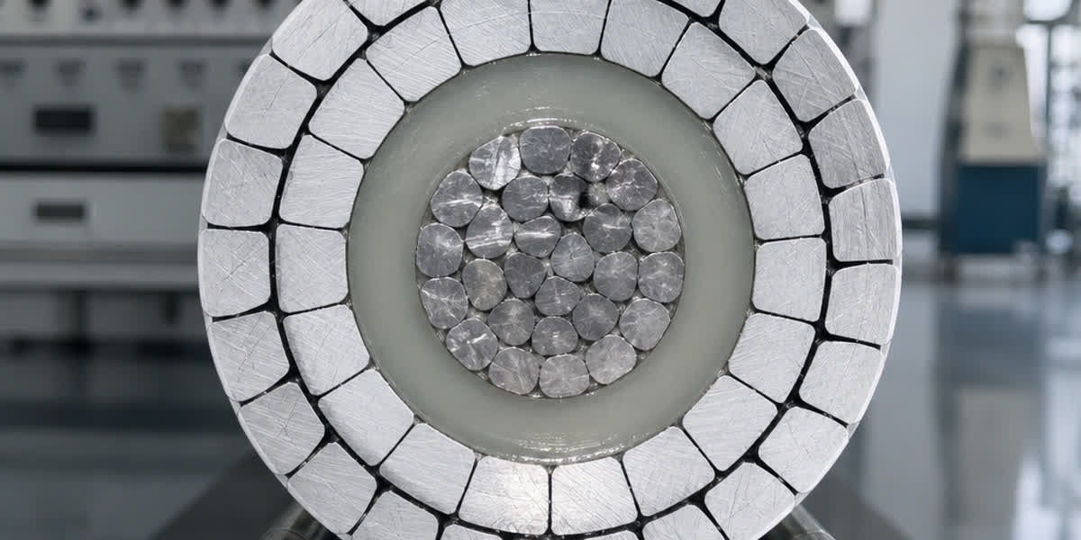
Engineers specify reinforced configurations from our ACSR conductor range utilizing high-strength steel cores (such as 54/7, 54/19, or special 28/7 and 30/7 strandings). By increasing the steel cross-sectional ratio to 30%–45% of total conductor area, the composite conductor achieves: 1. Dramatically Higher Ultimate Tensile Strength (UTS): Exceeding 130 kN to 220 kN for standard transmission cross-sections. 2. Elevated Effective Modulus of Elasticity ($E$): Increasing from ~70 GPa in high-aluminum strandings to 90–110 GPa in steel-reinforced designs, sharply curtailing total elastic elongation under heavy ice weight. 3. Reduced Composite Thermal Expansion Coefficient ($\alpha$): Mitigating summer sag while preserving winter mechanical reserve.
To ensure long-term structural survivability in damp, freezing corridors where atmospheric salts or industrial pollutants induce galvanic corrosion, the internal core must be constructed from high-tensile galvanized steel wire strands adhering to Class A, Class B, or Class C heavy zinc coating standards (ASTM A475, BS 183, IEC 60888), or modern aluminum-clad steel (ACS) wires (ASTM B415, IEC 61232).
AAAC vs. ACSR Under Heavy Radial Ice
All-Aluminum Alloy Conductors (AAAC), manufactured from heat-treated Al-Mg-Si alloys (such as 6201-T81 complying with ASTM B399 and IEC 61089), offer superior electrical conductivity-to-weight ratios and exceptional corrosion resistance. In moderate icing zones, our all-aluminum alloy AAAC conductors deliver excellent performance because their homogeneous material construction eliminates galvanic corrosion between steel and aluminum.
However, in heavy ice zones ($b \ge 25\text{ mm}$), AAAC conductors exhibit a key mechanical limitation: their modulus of elasticity ($E \approx 60\text{–}65\text{ GPa}$) is substantially lower than that of steel-cored ACSR ($E \approx 80\text{–}110\text{ GPa}$). Under identical 30 mm radial ice loading, an AAAC conductor experiences significantly larger elastic deformation, resulting in deeper vertical sag, greater loss of phase-to-phase and phase-to-ground electrical clearances, and increased risk of inter-phase flashover.
| Conductor Type | Stranding Ratio (Al/Steel or Alloy) | Elastic Modulus ($E$, GPa) | Tensile Strength (UTS, MPa) | Ice Loading Capability ($b \ge 25\text{ mm}$) | Recommended Application |
|---|---|---|---|---|---|
| Standard ACSR (26/7) | 6.0 : 1 | ~77 | 280 – 310 | Moderate ($b \le 15\text{ mm}$) | General transmission, temperate terrains |
| Heavy-Core ACSR (54/19) | 3.5 : 1 | ~98 | 380 – 430 | High ($b \le 35\text{ mm}$) | Heavy ice zones, mountain passes, long spans |
| High-Strength ACSR (30/7) | 2.5 : 1 | ~112 | 450 – 520 | Extreme ($b \ge 50\text{ mm}$) | Micro-terrain alpine gaps, severe ice corridors |
| AAAC (6201-T81) | Homogeneous | ~64 | 315 – 330 | Moderate ($b \le 15\text{ mm}$) | Coastal zones, moderate ice, unpolluted corridors |
| ACAR (Aluminum/Alloy) | Variable | ~68 | 290 – 340 | Moderate ($b \le 15\text{ mm}$) | High ampacity feeders, low-to-moderate ice |
4. Conductor Galloping: Aerodynamic Mechanisms and Dynamic Ice Shedding
While static vertical gravitational loading is severe, the dynamic instabilities provoked by ice accretion represent the most violent destruction mechanism on overhead transmission lines.
Conductor Galloping (导线舞动) Aeroelastic Mechanisms
Conductor galloping is a low-frequency (0.1 to 1.0 Hz), high-amplitude (0.1 to 1.0 times the static sag, reaching 0.5 to 8+ meters peak-to-peak) aeroelastic oscillation that occurs in wind speeds of 6 to 25 m/s when conductors are coated with an asymmetric layer of glaze or hard rime.
Galloping is governed by two complementary aerodynamic instability theories:
- Den Hartog Vertical Instability Criterion: When a crescent or teardrop ice layer deposits on the windward side of a conductor, it alters the cross-section into an aerodynamic airfoil. As the conductor oscillates vertically, its effective angle of attack $\alpha$ with respect to relative wind velocity changes. Den Hartog showed that aerodynamic instability occurs when the lift curve slope plus the drag coefficient becomes negative: $$\frac{dC_L}{d\alpha} + C_D < 0$$ Under this condition, aerodynamic lift acts in the direction of conductor motion, feeding net energy from the wind into the vertical oscillation modes.
- Nigol Torsional-Vertical Flutter Theory: In long transmission spans, conductors possess relatively low torsional stiffness ($GJ$). Wind-induced aerodynamic moment twists the conductor, matching the torsional natural frequency with a vertical natural vibration frequency. This modal frequency coupling causes violent, sustained single-loop or multi-loop standing wave galloping.
Dynamic Ice Shedding & Tension Shock Waves (脱冰跳跃)
When ice melts or detaches due to rising ambient temperatures, high line current Joule heating, or mechanical fracturing, the sudden release of mass is rarely uniform across the entire span. Asymmetric ice shedding occurs when ice falls from one half of a span or one phase while remaining frozen on adjacent spans or phases.
The consequences are two-fold: - Vertical Jump (跳跃): The sudden release of potential energy causes the unloaded conductor to whip violently upward. If vertical phase spacing is inadequate, the jumping phase infringes upon the electrical clearance ellipse of the upper phase, generating high-power phase-to-phase short-circuit flashovers that trip line protection breakers and burn conductor strands. - Unbalanced Longitudinal Tension: When ice sheds in Span 1 while Span 2 remains fully loaded with 30 mm of ice, a massive static and dynamic tension differential develops across the intermediate suspension tower. This generates severe longitudinal bending moments and torsional twisting forces on tower crossarms, which can result in tower structural deformation or cascading longitudinal tower collapses.
5. Hardware Countermeasures: Anti-Galloping & Mechanical Damping Devices
Mitigating ice storm disasters requires an integrated hardware defense system that combines aerodynamic detuning, mechanical spacing, and reinforced terminations.
Torsional Damper Detuners (TDD / 扭振减振防舞器)
Based on Nigol's torsional coupling theory, Torsional Damper Detuners (TDD) consist of calculated eccentric masses mounted on the conductor near suspension assemblies and at nodal quarter-points within the span. - Operating Principle: The eccentric mass of the TDD shifts the center of gravity of the conductor bundle and alters the natural torsional frequency of the span, de-synchronizing it from the vertical oscillation frequency. - Effect: By preventing the torsional twisting of the conductor under crosswinds, the ice profile cannot sustain the critical angle of attack required for aerodynamic energy transfer, effectively suppressing large-amplitude galloping.
Interphase Spacers (IPS / 相间间隔棒)
Interphase spacers are high-mechanical-strength, composite silicone-rubber insulating rods installed directly between vertically or horizontally adjacent phase conductors within the span. - Operating Principle: By physically coupling adjacent phases, interphase spacers prevent phase-to-phase clearance closure during both galloping oscillations and violent asymmetric ice-shedding jumps. - Structural Consideration: In heavy ice corridors, interphase spacers must possess high tensile and compressive buckling ratings (typically 40 kN to 70 kN mechanical failing load) to withstand the massive asymmetric vertical forces when one phase sheds ice while the lower phase remains loaded.
Engineers must specify high-performance anti-galloping and vibration fittings & hardware—including specialized heavy-duty suspension clamps with multi-directional articulation and preformed helical armor rods that distribute dynamic bending stresses away from clamp edges.
Tension Clamps, Compression Dead-Ends & Splices
Under heavy radial ice conditions, tension forces approach the ultimate design threshold of the line. Conventional bolted tension clamps are prone to slippage under dynamic cyclic shock loads. In heavy ice zones, line designers universally mandate full-tension compression dead-ends and heavy-duty cable lugs and compression connectors engineered to exceed 95% of the conductor's rated Ultimate Tensile Strength (UTS), verified through sustained tension and thermal cycling tests per IEC 61284 and ANSI C119.4.
| Mitigation Hardware | Operating Mechanism | Target Dynamic Phenomenon | Typical Placement in Span |
|---|---|---|---|
| Torsional Damper Detuner (TDD) | Shifts torsional frequency; offsets aerodynamic center | Multiloop conductor galloping | Quarter & third span nodal points |
| Interphase Spacer (IPS) | Mechanical restraint & inter-phase insulation | Ice-shedding jump & phase flashover | 1/3 and 2/3 span points |
| Airfoil / D-Spoilers | Disrupts aerodynamic lift profile | Single-loop wind galloping | Continuous helical wrap over 20-30% span |
| Heavy-Duty Spacer Dampers | Damps subconductor motion in bundled lines | Subspan oscillation & bundled line clash | Every 40–60 meters along bundle |
| Full-Tension Compression Clamps | High-pressure cold-weld hydraulic jointing | Conductor slippage under peak tension | Dead-end tension towers & substations |
6. OPGW and Shield Wire Coordination in Severe Freezing Corridors
Overhead Ground Wires (OHGW) and Optical Ground Wires (OPGW) occupy the uppermost position on transmission towers, fully exposed to oncoming supercooled wind currents. Because shield wires and OPGWs generally possess smaller outer diameters ($11\text{–}16\text{ mm}$) than phase conductors ($25\text{–}35\text{ mm}$), their ice-to-conductor mass ratio is significantly higher.
Consequently, smaller shield wires accumulate a proportionally heavier ice burden per unit mass, resulting in disproportionate increases in vertical sag. If this differential sag is not compensated during line profiling, the ground wire will sag into the phase conductors below, causing ground flashovers.
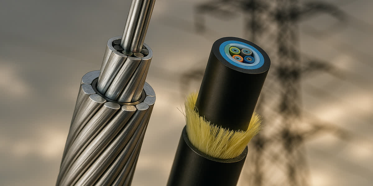
To maintain electrical shielding angle and clearance under heavy icing: 1. High-Strength Optical Ground Wire Design: Utilities install ruggedized OPGW cables incorporating high-yield aluminum-clad steel (ACS) and extra-high-strength galvanized steel wire strands. The optical fibers remain hermetically sealed inside thick-walled, laser-welded stainless steel tubes filled with thixotropic gel, completely isolated from severe structural tension strain up to 60% of RTS (Rated Tensile Strength). 2. Matching Sag-Tension Profiles: Sag-tension calculations for OPGW must be coordinated with the phase conductors across the full spectrum of temperatures (-30°C to +40°C) and radial ice thickness design conditions (0 mm to 35 mm). The OPGW must maintain a minimum vertical clearance of at least 1.0 to 1.5 times the basic impulse insulation level (BIL) air clearance above the top phase conductor under maximum icing.
7. Comprehensive Engineering Comparison & Selection Matrix
The following engineering decision matrix provides a comparative reference for transmission line engineers specifying conductor and shield wire materials across diverse atmospheric icing zones:
| Design Parameter / Criterion | Light Ice Zone ($b \le 10\text{ mm}$) | Moderate Ice Zone ($b = 15\text{–}20\text{ mm}$) | Heavy Ice Zone ($b = 25\text{–}35\text{ mm}$) | Extreme Micro-Terrain Zone ($b \ge 50\text{ mm}$) |
|---|---|---|---|---|
| Recommended Phase Conductor | Standard ACSR (26/7), AAAC (6201), ACAR | Standard ACSR (26/7, 54/7), AAAC | Heavy-Core ACSR (54/19, 30/7) | Ultra-High-Strength Steel Core ACSR (28/7, 30/7) |
| Conductor Steel Core Strength | Regular / High Strength (ASTM A475 Class A) | Extra High Strength (EHS / Class B Zinc) | Ultra High Strength (UHS / Class C / ACS) | Ultra High Strength ACS (ASTM B415) |
| Max Tension at Max Ice & Wind | $\le 40\%$ UTS | $\le 50\%$ UTS | $\le 55\%$ UTS | $\le 60\%$ UTS |
| Galloping Mitigation Hardware | Stockbridge Dampers (Vibration only) | Stockbridge Dampers + Optional TDD | TDD Detuners + Interphase Spacers (IPS) | TDD Detuners + IPS + Airfoil Spoilers |
| Phase Spacing Margin Multiplier | $1.0\times$ Standard Clearance | $1.2\times$ Standard Clearance | $1.4\times$ to $1.6\times$ Standard Clearance | $\ge 1.8\times$ Enhanced Vertical Spacing |
| OPGW Shield Wire Construction | Standard ACS/Alloy Optical Tube | Reinforced ACS Wire Stranding | Heavy ACS Tube + Multi-Wire Steel Armor | High-Strength Stainless Tube with Double ACS Armor |
| Typical Failure Risk in Storm | Negligible structural risk | Minor galloping / subspan clash | Asymmetric ice jump, phase flashover | Tower crossarm collapse, tensile rupture |
8. Frequently Asked Questions (FAQ)
Q1: Why does a smaller diameter conductor accumulate a higher ice-to-conductor weight ratio than a large conductor?
A: Ice accretion collision efficiency depends on the aerodynamic flow field around the cylindrical wire. For smaller diameter conductors or ground wires (e.g. 10–14 mm), supercooled air streamlines diverge less abruptly around the cylinder. Droplets with sufficient inertia cannot follow the curving streamlines and collide directly with the wire surface, resulting in a higher droplet collection efficiency ($E_c$). For large diameter conductors (e.g. 30–40 mm), supercooled air streamlines diverge more widely around the frontal obstacle, carrying smaller droplets around the perimeter without impact. Consequently, shield wires and small distribution conductors experience a higher radial ice accretion rate relative to their cross-sectional area, making their percentage weight increase much more dramatic.
Q2: What is the primary difference between Aeolian vibration and Conductor Galloping?
A: While both are wind-induced aerodynamic oscillations, their excitation physics and structural impacts are fundamentally different: - Aeolian Vibration: Caused by high-frequency alternating vortex shedding (von Kármán vortices) behind a bare circular conductor in steady, low-velocity laminar winds (1 to 7 m/s). It features high frequencies (10 to 100 Hz) and minute amplitudes (fractions of a millimeter up to one conductor diameter). It results in long-term bending fatigue failure of conductor strands at suspension clamps over millions of cycles. - Conductor Galloping: Caused by aerodynamic lift and torsional instability acting on an asymmetric, ice-coated conductor in moderate to high winds (6 to 25 m/s). It features low frequencies (0.1 to 1.0 Hz) and massive vertical amplitudes (0.5 to 8+ meters). It results in immediate, violent structural destruction: phase-to-phase electrical flashovers, broken insulator strings, and tower crossarm failure within minutes or hours.
Q3: When should transmission engineers specify high-strength steel-core ACSR over AAAC in freezing mountain corridors?
A: When the design radial glaze or rime ice thickness exceeds 20 mm, high-strength steel-core ACSR (such as 54/19 or 30/7 strandings) is strongly recommended over AAAC. Because AAAC is composed entirely of aluminum alloy (elastic modulus $E \approx 64\text{ GPa}$), its elastic elongation under heavy combined ice and wind load is significantly greater than that of steel-cored ACSR ($E \approx 95\text{–}110\text{ GPa}$). The deeper sag of AAAC under heavy ice requires taller transmission towers or reduced span lengths to preserve mandatory electrical ground clearances. Furthermore, the high ultimate tensile strength of reinforced steel-core ACSR provides a critical structural safety margin against tensile rupture during extreme unpredicted icing events.
Q4: Can anti-galloping Torsional Damper Detuners (TDD) be installed on existing transmission lines without reconductoring?
A: Yes. One of the greatest engineering advantages of Torsional Damper Detuners (TDD) is that they can be retrofitted directly onto existing, energized or de-energized overhead transmission spans. By performing a span-specific modal dynamic simulation considering conductor diameter, span length, tension, and local wind vectors, engineers calculate the exact eccentric mass weights and nodal mounting locations. Installing TDDs modifies the span's torsional response to decouple torsional flutter from vertical modes, providing effective galloping suppression without requiring expensive conductor replacement or structural tower reinforcement.
9. Conclusion: Engineering Reliable Overhead Lines in Freezing Climates
Designing overhead transmission and distribution networks to withstand extreme atmospheric icing requires a rigorous, multi-disciplinary systems approach. From accurate meteorological micro-terrain modeling under IEC 60826 to the structural selection of high-tensile steel-reinforced conductors, every component must function synergistically to resist gravitational overloads, dynamic ice-shedding shocks, and wind-induced galloping.
Zhengzhou SiTong Cable Co., Ltd. (SiTong Cable) has engineered and manufactured premium bare overhead conductors, optical ground wires, and transmission accessories for critical electrical grid projects in more than 80 countries worldwide. Utilizing state-of-the-art rigid frame stranding lines, precision automated pre-forming technology, and rigorous metallurgical quality testing complying with ISO 9001, ASTM, BS, IEC, and DIN standards, SiTong Cable delivers tailored overhead conductor solutions engineered to endure the world's harshest winter environments.
👉 Browse our complete ACSR conductor range 👉 Explore high-tensile galvanized steel wire strands 👉 Contact our engineering and technical support team
📬 Sales & Engineering Inquiries: sales@sitongcable.com | 📞 Phone: +86-371-69176007