Submarine Power Cable Engineering Guide: Offshore Wind Export, Interconnectors, Radial Water Barriers, Dynamic Armoring & CIGRE TB 623 Standards
Submarine Power Cable Engineering Guide: Offshore Wind Export, Interconnectors, Radial Water Barriers, Dynamic Armoring & CIGRE TB 623 Standards
Submarine power cables represent the pinnacle of high-voltage transmission engineering, operating under hydrostatic pressures exceeding 50 bar, severe cyclic hydrodynamic forces, aggressive saline corrosion, and mechanical threats from marine anchoring and commercial trawling. Whether delivering bulk renewable power from offshore wind farms to shore or establishing high-voltage interconnectors across international straits, subsea power links demand zero-tolerance reliability over design lifespans surpassing 30 to 40 years. Designing and manufacturing an underwater power transmission system requires mastering radial and longitudinal water-blocking physics, heavy mechanical tensile armoring, and composite fiber-optic communication integration.
As a leading global cable manufacturer, Zhengzhou SiTong Cable Co., Ltd. (SiTong Cable) engineers and delivers advanced power transmission systems designed according to stringent CIGRE, IEC, and IEEE standards. In this comprehensive technical guide, SiTong Cable's high-voltage engineering team examines the core structural anatomy of submarine power cables, radial and longitudinal water-barrier physics, dynamic versus static mechanical armoring, thermal modeling under subsea seabeds, installation mechanics, and international qualification standards.
1. Submarine Cable Architectures: MV Array, HV Export & Interconnectors
Underwater electrical transmission networks are broadly categorized into three core functional classifications:
+----------------------------------------------------------------------------------------------------+
|                                    SUBMARINE CABLE TAXONOMY                                        |
+-----------------------------------+--------------------------------+-------------------------------+
| Feature                           | Medium Voltage (MV) Array      | High Voltage (HVAC) Export    | High Voltage (HVDC) Links     |
+-----------------------------------+--------------------------------+-------------------------------+
| Typical Voltage Rating            | 33 kV, 66 kV (Um up to 72.5 kV)| 110 kV, 132 kV, 220 kV, 275 kV| +/-320 kV, +/-525 kV          |
| Network Application               | Wind Turbine to Offshore Sub   | Offshore Sub to Onshore Grid  | Long-Distance Subsea Link     |
| Practical Transmission Distance   | 1 km - 5 km per string         | 15 km - 100 km (reactive limit)| > 80 km up to 800+ km         |
| Core Construction                 | 3-Core with integrated FO      | 3-Core or 3x Single-Core      | Bipolar Pair (2x Single-Core) |
| Dominant Insulation               | Wet-design or Dry TR-XLPE/EPR  | Triple-extruded Superclean XLPE| Cross-linked or Mass-Impreg.  |
| Primary Limiting Factor           | Bending radius in J-tubes      | Charging reactive current     | Converter station capital cost|
+-----------------------------------+--------------------------------+-------------------------------+
In medium-voltage inter-array networks, 66 kV has rapidly supplanted legacy 33 kV systems across utility-scale offshore wind farms. Doubling the array operating voltage halves current magnitude for an equivalent power transfer, dramatically shrinking conductor cross-sections, minimizing thermal dissipation, and enabling up to 10–12 wind turbines per array string. For large-scale land installations, engineers cross-reference our underground cable selection guide to evaluate terrestrial grid tie-ins.
High-voltage alternating current (HVAC) export systems (132 kV to 275 kV) are the workhorses of offshore wind generation up to distances of 70–90 km. Beyond this critical threshold, high reactive charging currents ($I_c = 2\pi f C V$) consume the thermal ampacity of the conductors, necessitating either expensive offshore shunt compensation reactors or a transition to High-Voltage Direct Current (HVDC) systems based on Voltage Source Converters (VSC).
2. Anatomical Breakdown: Layer-by-Layer Subsea Construction
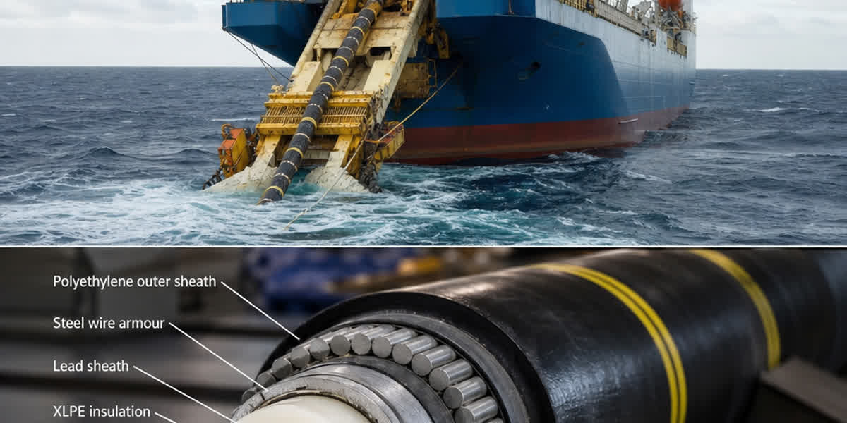
A high-performance submarine power cable is an engineered multi-barrier composite structure:
[ Copper/Aluminum Conductor + Swellable Powder Water-Block ]
   --> [ Triple Co-Extruded Superclean Cross-Linked Insulation (Conductor Shield + XLPE + Semi-Con) ]
         --> [ Longitudinal Semi-Conducting Swellable Tape Buffer ]
               --> [ Hermetic Radial Barrier: Extruded Lead Alloy (Pb) or Welded Corrugated Metal ]
                     --> [ Semiconductive / Polyethylene Anti-Corrosion Inner Separation Sheath ]
                           --> [ Bedding Layer + Integrated Optical Ground Wire (OPGW) / Fiber Units ]
                                 --> [ Heavy Galvanized Steel Wire Tensile Armor (Single/Double Layer) ]
                                       --> [ Bitumen Compound Coating + Heavy Polypropylene Yarn Outer Wrap ]
2.1 Conductor Stranding and Longitudinal Water-Blocking
Conductors are manufactured from high-purity electrolytic copper (Cu-ETP, ASTM B3) or high-conductivity electrical grade aluminum (Al-1350, ASTM B231). In submarine environments, circular compact or shaped Keystone (Conci) designs are utilized to achieve packing factors exceeding 93–96%.
To prevent catastrophic capillary propagation of seawater in the event of an anchor drag or external hull impact that breaches the outer sheath, all interstitial voids between conductor strands are continuously packed with semi-conductive water-swellable powders, swelling yarns, or hydrophobic viscous blocking compounds. Under IEC 60502-2 and CIGRE guidelines, a longitudinal water penetration test requires that no water ingress extends beyond 3 meters under a 1-meter hydrostatic head over a 10-day cyclic thermal duration.
For overhead transition spans connecting subsea landfalls to high-altitude transmission towers, utilities deploy our high-tensile ACSR conductor range or alloy-reinforced AAAC conductor systems to bridge coastal escarpments.
2.2 Triple Co-Extrusion & Superclean XLPE Insulation
High-voltage submarine cable cores undergo simultaneous single-head triple-extrusion (conductor screen, insulation, insulation screen) in an enclosed cleanroom environment (Class 100 / ISO 5) utilizing dry-curing nitrogen vulcanization lines. The compound utilizes high-purity, superclean cross-linked polyethylene (XLPE) or Tree-Retardant XLPE (TR-XLPE).
The elimination of micro-voids, contaminant inclusions (>50 micrometers), and inner-screen protrusions is mission-critical. Under the high electrical stress fields encountered in 132 kV–220 kV subsea cables (operating stresses exceeding 8–15 kV/mm at the conductor screen), any microscopic defect serves as an initiation site for electrical treeing, exacerbated by cyclic mechanical flexure.
2.3 Radial Water Barriers: Lead Alloy Sheath vs. Welded Metal Sheaths
Seawater accelerates electrochemical treeing degradation in cross-linked polyolefins if moisture molecules migrate into the dielectric core. Therefore, high-voltage submarine cables employ absolute hermetic moisture barriers: 1. Extruded Lead Alloy Sheath (Alloy E per BS 801 or Cu-Pb per DIN 17640): Extruded continuously over the insulated core. Lead provides extraordinary radial impermeability, high chemical stability in saline media, and outstanding fatigue resistance under cyclic bending. 2. Smooth / Corrugated Welded Copper or Aluminum Sheaths: Used where total cable weight reduction is critical, or for enhanced short-circuit earth fault capacity. 3. Semi-Dry Polylaminate (AL-PE / Cu-PE) Foils: Limited strictly to medium-voltage array cables where lower operational electrical stresses permit lighter-weight wet/damp structural configurations.
3. Dynamic vs. Static Armoring Mechanics and Hydrodynamic Stability
+--------------------------------------------------------------------------------------------------------+
|                                SUBMARINE CABLE ARMORING ARCHITECTURE                                   |
+-----------------------+---------------------------------------+----------------------------------------+
| Engineering Parameter | Static Seabed Cable                   | Dynamic Floating Offshore Cable        |
+-----------------------+---------------------------------------+----------------------------------------+
| Installation Context  | Buried in seabed trench / Rock riprap | Suspended water column (Lazy-S / Lazy-Wave)|
| Dynamic Motion        | Quiescent post-installation           | 10^7 wave/vortex-induced cycles/year   |
| Primary Stress Mode   | Tensile laying stress + anchor impact | Multi-axial cyclic tension-torsion-bend|
| Armor Construction    | 1 or 2 layers Galvanized Steel Wire   | Double counter-wound torque-balanced GSW|
| Armor Wire Tensile Rm | 340 - 550 N/mm2 (ASTM A411 / BS EN)   | 1200 - 1600 N/mm2 (High-tensile steel) |
| Lay Length & Angle    | Short lay (7 - 9 degrees)             | Optimized balance (14 - 18 degrees)    |
| Ancillary Hardware    | Cast iron articulated burial pipes    | Bending stiffeners, buoyancy modules   |
+-----------------------+---------------------------------------+----------------------------------------+
3.1 Mechanical Tensile Load Calculation During Cable Laying
During maritime cable deployment from dedicated dynamically positioned (DP2) cable-laying vessels, the cable is subjected to severe axial tensile loading combined with bending over the stern chute or through vertical lay tensioners. The total dynamic laying tension $T_{max}$ experienced at the vessel chute is governed by:
$$T_{max} = w_w \cdot D + \frac{1}{2} C_d \rho_w d_c v_v^2 + T_{res}$$
Where: - $w_w$ is the submerged cable weight per unit length in seawater ($N/m$), - $D$ is water depth ($m$), - $C_d$ is the hydrodynamic drag coefficient, - $\rho_w$ is seawater density ($1025\ kg/m^3$), - $d_c$ is overall cable outer diameter ($m$), - $v_v$ is vessel lay velocity through water ($m/s$), - $T_{res}$ is the residual bottom tension required to prevent cable looping or slack buckle ($typically\ 10 - 30\ kN$).
Heavy galvanized round steel wires applied with bituminous flooding protect against galvanic corrosion. For deep installations and guyed marine transition structures, engineers specify our galvanized steel wire strand to anchor coastal towers and marine pull-in rigs.
3.2 Dynamic Inter-Array Cables for Floating Wind Turbines
As offshore wind ventures into deep waters (>60 meters), fixed-bottom monopiles and jacket foundations give way to floating offshore wind turbines (FOWT). Floating platforms exhibit continuous 6-degree-of-freedom motions (surge, sway, heave, roll, pitch, yaw).
Dynamic subsea cables deployed in Lazy-Wave configurations with distributed subsurface buoyancy modules must resist extreme dynamic bending fatigue. Counter-wound double-layer galvanized steel armor wires are manufactured with precisely matched lay angles to achieve a torque-balanced structure, preventing dynamic torsion and catastrophic "bird-caging" of the tensile wires under cyclic tension.
4. Integrated Fiber-Optic Elements and Distributed Temperature Sensing (DTS)
Modern submarine power links are composite power and telecommunications conduits. High-density fiber-optic bundles are integrated into the internal interstitial fillers between the three phase cores:
[ Copper Conductor ]      [ Copper Conductor ]
        \                     /
         [ Stainless Steel Tube with Optical Fibers ]
                   |
         [ Copper Conductor ]
- Fiber Telecommunications & Control: Singlemode fibers (ITU-T G.652.D or G.655) encased in hermetically sealed, gel-filled stainless steel (SUS316L) micro-tubes provide terabit-class SCADA, grid teleprotection, and commercial data transmission. In overhead lines, this dual function is mirrored by OPGW optical ground wire cables.
- Distributed Temperature Sensing (DTS): Utilizing Raman optical time-domain reflectometry (OTDR), an optical fiber acts as a continuous, linear temperature sensor across the entire subsea route (up to 50–70 km per channel). DTS monitors real-time hot-spots along the cable profile with 1-meter spatial resolution and +/-0.5 deg C thermal precision.
- Distributed Acoustic Sensing (DAS): Rayleigh backscattering detects acoustic and seismic signatures along the subsea route, warning grid operators in real time of approaching anchor dragging, commercial dredging, or seabed unburial.
For land connections and onshore terminal distribution cabinets, contractors match submarine fiber and power terminations using specialized cable lugs and compression hardware and heavy-duty transmission fittings & hardware.
5. Thermal Modeling, Seabed Burial & Cable Ampacity (IEC 60287)
Subsea cables cannot be cooled by ambient ocean currents once buried beneath the seabed for mechanical protection. In accordance with IEC 60287 and CIGRE guidelines, thermal ampacity depends heavily on the seabed sediment thermal resistivity:
+-----------------------------------------------------------------------------------------------+
|                                SEABED THERMAL PROFILE & AMPACITY IMPACT                       |
+---------------------------+-----------------------------------+-------------------------------+
| Seabed Sediment Type      | Thermal Resistivity Rho (K*m/W)   | Ampacity Derating Factor      |
+---------------------------+-----------------------------------+-------------------------------+
| Open seawater (unburied)  | 0.29                              | 1.30 (Enhanced convective)    |
| Saturated coarse marine sand | 0.7 - 0.8                      | 1.00 (Standard design baseline)|
| Saturated clay / silt     | 0.9 - 1.2                         | 0.88 - 0.94                   |
| Dry sand dunes / Landfall | 1.5 - 2.5                         | 0.65 - 0.78 (Critical hot-spot)|
| Horizontal Directional Drill (HDD) | 1.2 - 1.8                | 0.72 - 0.82 (Grout dependent) |
+---------------------------+-----------------------------------+-------------------------------+
The current-carrying capacity $I$ under continuous equilibrium is expressed by IEC 60287:
$$I = \left[ \frac{\Delta \theta - W_d \left( \frac{1}{2} T_1 + n(T_2 + T_3 + T_4) \right)}{R_{ac} T_1 + n R_{ac} (1 + \lambda_1) T_2 + n R_{ac} (1 + \lambda_1 + \lambda_2)(T_3 + T_4)} \right]^{0.5}$$
Where: - $\Delta \theta$ is conductor permissible temperature rise above ambient seabed ($90^\circ\text{C} - 15^\circ\text{C} = 75\text{ K}$ for XLPE), - $W_d$ represents dielectric losses per unit length ($W/m$), - $R_{ac}$ is alternating current electrical resistance at maximum operating temperature ($\Omega/m$), - $T_1, T_2, T_3, T_4$ are the thermal resistances per unit length of insulation, inner sheath, bedding, and external seabed medium ($K\cdot m/W$), - $\lambda_1, \lambda_2$ represent sheath and armoring loss factors relative to conductor losses.
At the onshore landfall transition—where the submarine cable exits open water via Horizontal Directional Drilling (HDD) conduits—the thermal resistivity of terrestrial soil frequently spikes to $1.5\text{–}2.5\text{ K}\cdot m/W$. This landfall transition zone constitutes the critical bottleneck (hot-spot) of the entire transmission link. Engineers counter this derating by either increasing conductor cross-section (e.g., from $800\text{ mm}^2$ subsea to $1200\text{ mm}^2$ at landfall) or pumping bentonite-based thermally conductive grouts into the landfall duct. In regional medium-voltage distribution grids running overhead to shore, utilities also integrate insulated aerial bundled cables (ABC) to eliminate coastal salt-fog flashovers.
6. Marine Installation, Burial Protection & CIGRE TB 623 Testing Standards
6.1 Seabed Trenching & Burial Protection Methodologies
Over 80% of reported subsea cable outages result from human maritime activity—principally ship anchors, bottom trawl doors, and aggregate dredging. Cables are buried beneath the seabed using three main deployment methods: 1. Jet Trenching (ROV / Sled): High-pressure water jets fluidize sandy or soft clay seabed sediments beneath the pre-laid cable, allowing it to sink to a target burial depth of 1.5 to 3.0 meters. 2. Mechanical Chain/Wheel Cutting: Heavy diamond-tipped chain cutters carve trenches through hard bedrock, calcarenite, or compacted coral formations. 3. Rock Placement (Rip-Rap): In zones where trenching is infeasible, specialized fall-pipe vessels dump graded quarry rock berms over the cable to dissipate anchor drop kinetic energies.
6.2 CIGRE TB 623 & IEC 60840 / IEC 62067 Qualification Rigor
Before deploying offshore, submarine cable designs must satisfy the rigorous type testing criteria specified in CIGRE Technical Brochure 623 ("Recommendations for mechanical testing of submarine cables") and IEC 60840 / IEC 62067:
[ Tensile Coiling & Reverse Bending Rig (3 cycles over mandrels at dynamic laying tension) ]
                                   |
[ Tensile Load Test at 1.3x Design Laying Tension (No armor slippage or conductor necking) ]
                                   |
[ Electrical Type Test: 20 Heat Cycles at 2.5x U0 with Impulse Voltage (105 deg C conductor) ]
                                   |
[ Water Penetration Test: 10-day cyclic heating at 1 bar hydrostatic pressure across 3m length ]
                                   |
[ External Visual & Microscopic Dissection (Zero shield indentation, micro-voids, or delamination) ]
7. Comparative Technical Specifications: 33kV, 66kV, 132kV & 220kV Cables
The engineering parameters below illustrate typical three-core copper XLPE submarine power cables manufactured by SiTong Cable:
+-----------------------------------------------------------------------------------------------------------------+
|                         REPRESENTATIVE SUBMARINE POWER CABLE TECHNICAL SPECIFICATIONS                            |
+------------------------------------+------------------+------------------+------------------+-------------------+
| Parameter                          | 33 kV Array      | 66 kV Array      | 132 kV Export    | 220 kV Export     |
+------------------------------------+------------------+------------------+------------------+-------------------+
| Nominal System Voltage ($U$)       | 33 kV            | 66 kV            | 132 kV           | 220 kV            |
| Maximum Continuous Voltage ($U_m$) | 36 kV            | 72.5 kV          | 145 kV           | 245 kV            |
| Conductor Cross-Section ($mm^2$)   | 3 x 400 Cu       | 3 x 630 Cu       | 3 x 800 Cu       | 3 x 1000 Cu       |
| Conductor Design                   | Compact Circular | Compact Circular | Segmental/Keyst. | Milliken Compact  |
| Nominal Insulation Thickness ($mm$)| 8.0 mm           | 11.0 mm          | 18.0 mm          | 24.0 mm           |
| Radial Moisture Barrier            | Lead Alloy E     | Lead Alloy E     | Lead Alloy E     | Lead Alloy E      |
| Armoring Wire Diameter ($mm$)      | 5.0 mm GSW       | 6.0 mm GSW       | 6.0 mm GSW (x2)  | 7.0 mm GSW (x2)   |
| Overall Cable Diameter ($mm$)      | 115 mm           | 142 mm           | 210 mm           | 265 mm            |
| Submerged Weight in Seawater ($kg/m$)| 24.5 kg/m      | 38.2 kg/m        | 78.5 kg/m        | 118.0 kg/m        |
| Maximum Continuous Ampacity (Seabed)| 610 A           | 790 A            | 885 A            | 1040 A            |
| Continuous Power Transfer ($MVA$)  | ~35 MVA          | ~90 MVA          | ~202 MVA         | ~395 MVA          |
| Integrated Optical Fibers          | 24 / 48 SMF      | 48 / 96 SMF      | 48 / 96 SMF      | 96 / 144 SMF      |
+------------------------------------+------------------+------------------+------------------+-------------------+
8. Why Global Utilities Partner with SiTong Cable for Subsea & Grid Projects
Zhengzhou SiTong Cable Co., Ltd. operates high-precision manufacturing facilities equipped with vertical continuous vulcanization (VCV) towers, automated heavy multi-wire armorers, and automated cleanroom compounding plants.
- Certified Quality Management: Manufacturing compliant with ISO 9001, ISO 14001, and ISO 45001, with products certified by KEMA, CE, and national grid test laboratories.
- Full Electrical Portfolio: From complex submarine cables and medium voltage power cables to overhead tree wire conductors and concentric service cables.
- Engineering and Logistics Support: Comprehensive testing, continuous delivery in long continuous spool lengths, and field termination guidance across global markets.
9. Frequently Asked Questions (FAQ)
Q1: What is the primary difference between a "wet design" and a "dry design" submarine cable?
A "dry design" submarine cable incorporates an extruded radial metallic barrier (typically a continuous extruded lead alloy sheath or hermetically welded corrugated metallic tape) that provides 100% impermeability to moisture. A "wet design" cable omits the continuous radial metallic sheath, relying solely on water-tree retardant polymers (TR-XLPE or EPR) and semi-permeable polymer sheaths. Dry designs are standard for high-voltage (HV/EHV) systems ($U \ge 66\text{ kV}$) to guarantee an operating life of 40+ years without water-tree degradation. Wet designs are occasionally utilized in medium-voltage array circuits ($U \le 33\text{ kV}$) to decrease cable weight and manufacturing costs.
Q2: Why are lead alloy sheaths still favored over aluminum or copper in submarine cables?
Extruded lead alloys (such as Alloy E per BS 801) offer a unique combination of engineering properties critical for maritime survival: continuous extrusion without longitudinal welds, unmatched chemical inertia against aggressive saline and acidic marine soils, and exceptional metallurgical ductility. Lead absorbs repeated micro-bending and cyclic mechanical flexure during vessel spalling, chute deployment, and hydrodynamic wave excitation without work-hardening, micro-cracking, or fatiguing.
Q3: How is fiber-optic communication integrated without being damaged by heavy power cable armoring?
Optical fibers are loosely buffered inside stainless steel (SUS316L) micro-tubes filled with thixotropic hydrogen-scavenging gel. These metallic fiber units are nested within the interior synthetic filler profiles (typically extruded high-density polyethylene or polypropylene matrix fillers) nestled in the central crevices between the three power cores. This internal position shields the delicate glass fibers from external mechanical impact, radial armor pressure, and tensile laying loads.
Q4: Why is 66 kV superseding 33 kV for offshore wind farm inter-array systems?
Operating offshore inter-array collectors at 66 kV instead of 33 kV doubles transmission voltage, which halves current for identical megawatt turbine capacities ($P = \sqrt{3} V I \cos\phi$). Halving conductor current cuts internal $I^2 R$ electrical resistive losses by 75%. This allows wind farm operators to double the number of high-capacity turbines (e.g., 12 MW–16 MW units) connected to a single cable collector string, decreasing the number of offshore substation J-tube entries, reducing offshore switchgear footprints, and slashing capital expenditure.
Q5: What is the typical burial depth for submarine power cables, and how is it determined?
Submarine cables are typically buried between 1.0 meter and 3.0 meters below the seabed. In areas with high-density shipping traffic, aggregate anchorages, or commercial beam trawling, burial depths can exceed 4.0 to 5.0 meters. The specific burial depth is established through a comprehensive Cable Burial Risk Assessment (CBRA), which evaluates vessel AIS traffic densities, anchor penetration models, sub-bottom geology, and seabed mobile sand wave dynamics.
10. Technical Selection & Engineering Support
Engineering a resilient, long-distance submarine power transmission link requires precise integration of electrical insulation physics, marine mechanics, and thermal modeling. Contact the SiTong Cable engineering team to discuss custom cable specifications, continuous spool lengths, CIGRE type-testing documentation, and project tenders.
👉 Browse our complete power cable product portfolio
👉 Explore our heavy-duty transmission fittings & hardware
👉 Consult SiTong Cable engineering team
📬 Sales & Project Inquiries: sales@sitongcable.com | 📞 Phone: +86-371-69176007