Guía de Campo Completa de Instalación y Mantenimiento del Conductor ACSS para Líneas Aéreas de Alta Temperatura y Baja Flecha
Guía de Campo Completa de Instalación y Mantenimiento del Conductor ACSS para Líneas Aéreas de Alta Temperatura y Baja Flecha
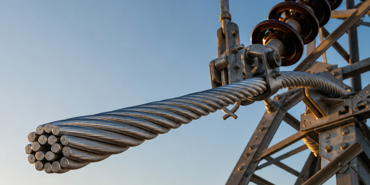
El conductor ACSS (Aluminio Recocido con Alma de Acero, Annealed Steel Supported) es la tecnología HTLS (Alta Temperatura Baja Flecha) más madura comercialmente: ofrece entre un 50% y un 100% más de ampacidad que un conductor ACSR convencional del mismo tamaño y admite operación continua a 200°C. Esta guía de campo cubre el flujo de trabajo completo de instalación y mantenimiento de líneas aéreas con ACSS — desde recepción y almacenamiento, tendido, asentamiento de rodilla (KCM), ensayos y el plan de mantenimiento de por vida — y está dirigida a ingenieros de transmisión, cuadrillas de tendido y responsables de mantenimiento.
Introducción
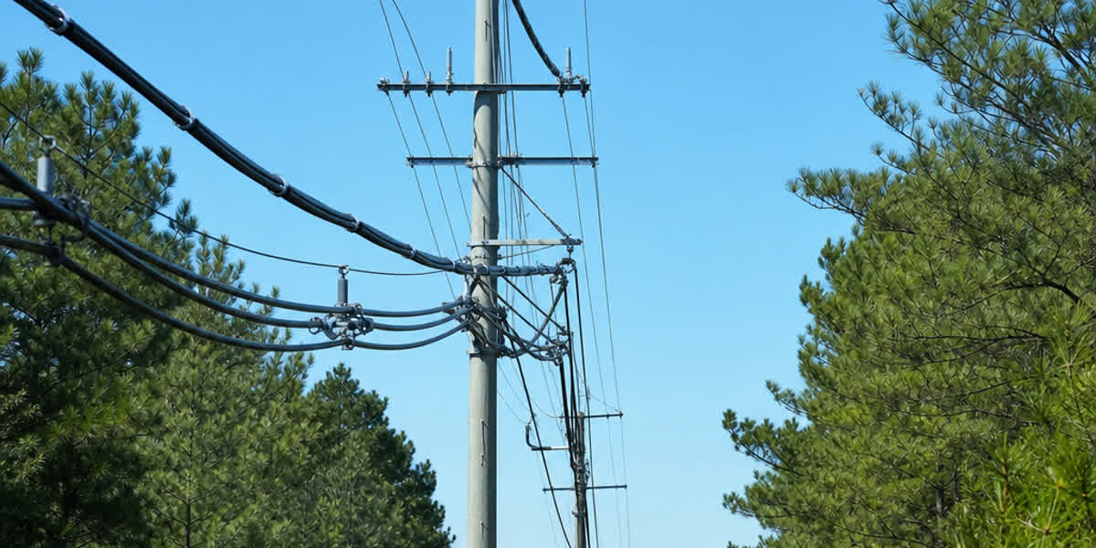
La re-potenciación de líneas de transmisión con ACSS es una de las prácticas de más rápido crecimiento en la ingeniería de redes modernas. Como el ACSS utiliza los mismos nombres clave, diámetros exteriores y pesos que el conductor ACSR estándar, las torres existentes suelen reutilizarse sin modificación estructural, lo que lo convierte en la ruta de menor coste para lograr un aumento de capacidad de 1,5 a 2 veces. Sin embargo, el ACSS no se instala exactamente igual que el ACSR. Los alambres de aluminio totalmente recocido (templado O) se comportan de forma muy distinta bajo tensión y temperatura, y cada fase del trabajo — tensión de tendido, selección de poleas, herrajes de anclaje y el primer ciclo de calentamiento — debe considerar el mecanismo de relajación plástica del conductor.
Esta guía es el complemento de campo de nuestra Guía Técnica Completa del Conductor ACSS, que aborda en profundidad normas, especificaciones y selección. Aquí nos centramos en la ejecución práctica: qué verificar en la bobina, qué herramientas llevar, cómo calcular la tensión de tendido con margen de fluencia de rodilla (KCM), cómo ejecutar el ciclo de asentamiento y qué inspeccionar durante los próximos 10 años. Todos los procedimientos referencian IEEE 524 (el Capítulo 15 está dedicado a la instalación de ACSS), ASTM B857, IEC 61089, IEEE 738 y CIGRE TB 244/324.
Preparación Previa a la Instalación
Recepción y Almacenamiento
La primera diferencia importante entre ACSS y ACSR comienza en el almacén: el aluminio recocido es más blando y se daña con más facilidad que el alambre estirado en frío. Siga esta lista de inspección en la recepción:
| Elemento de control | Criterio de aceptación |
|---|---|
| Estado de la bobina | Sin tablones rotos ni golpes; girar la bobina sobre su eje, nunca apoyada en el suelo |
| Superficie del conductor | Sin abrasiones, cocas ni desorganización de capas; el acabado mate del recocido es normal, no un defecto |
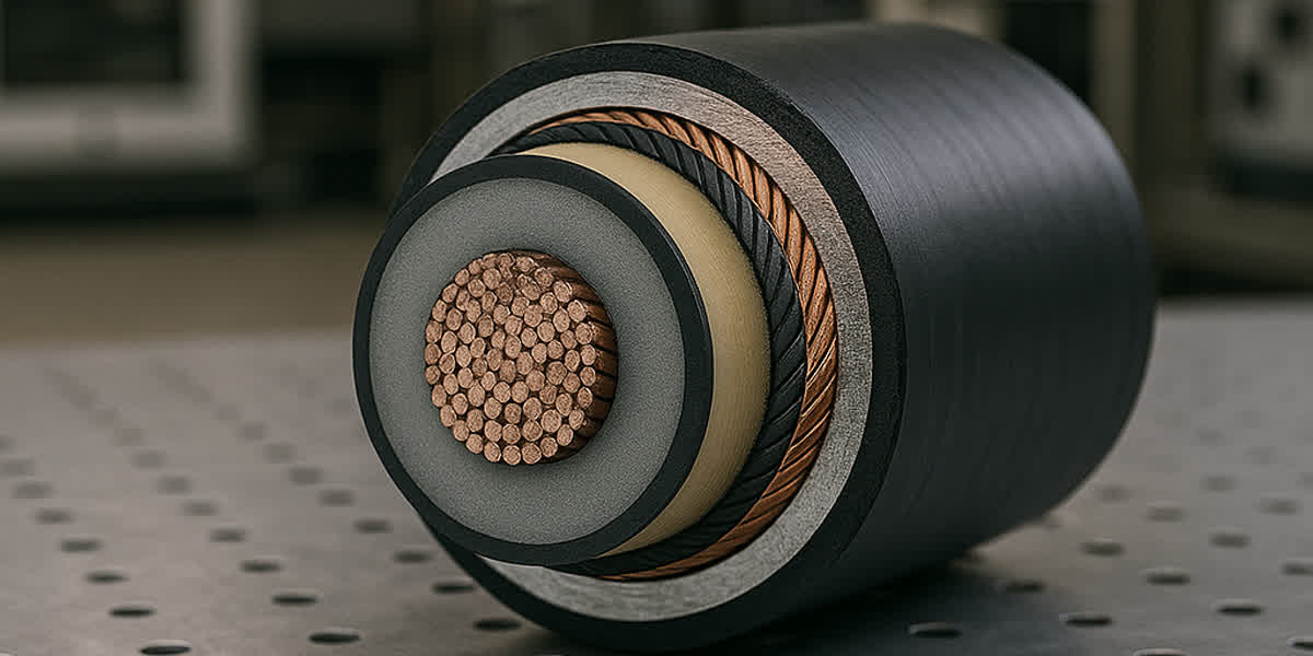
| Estado del alma | Alambres de acero galvanizado o aluminizado sin óxido ni daños del recubrimiento |
| Sellos de extremo | Ambos extremos sellados; si están abiertos, comprobar entrada de humedad y oxidación |
| Documentación | Certificado de ensayo de fábrica según ASTM B857 (tracción, conductividad ≥63% IACS, cableado) |
Reglas de almacenamiento: almacenar las bobinas en posición vertical sobre superficie firme y drenada. Si el almacenamiento supera los 6 meses, girar cada bobina 180° cada 3 meses para evitar la fluencia del alma en las capas inferiores. Proteger del sol: la temperatura ambiente elevada acelera la oxidación del aluminio — mantener por debajo de 40°C cuando sea posible. La temperatura mínima de instalación es de –10°C; por debajo de ella el aluminio recocido se vuelve frágil y se requieren procedimientos especiales de calentamiento.
Lista de Herramientas y Equipos
| Categoría | Equipo | Notas de aplicación |
|---|---|---|
| Tendido | Máquina de tracción, freno con dinamómetro, piloto sintético (nunca cable de acero en contacto con el conductor) | Tracción máxima según diseño (típicamente 15%–25% de la carga de rotura RTS) |
| Poleas | Poleas de tendido con diámetro ≥25× el diámetro exterior del conductor, giratorios, manguitos de tracción | ACSS admite 25× frente a 30× del ACSR por su flexibilidad, nunca menos de 25× |
| Engarce | Mordazas de compresión de tensión total, prensa hidráulica ≥100 MPa, matrices para alma de acero y aluminio | Las matrices son específicas por tamaño — el aluminio recocido requiere menor presión que el ACSR |
| Herrajes | Anclajes, grapas de suspensión, varillas de armadura, amortiguadores Stockbridge | TODOS los herrajes deben estar clasificados para 200°C continuos / 250°C de emergencia |
| Medición | Reglas de flecha o telémetro láser, dinamómetro, pirómetro/termopar, cámara infrarroja | La flecha se mide con instrumentos, nunca a ojo |
| Puesta a tierra | Conjuntos de puesta a tierra portátiles, mantas conductoras | Tensión inducida en líneas desenergizadas junto a circuitos en tensión |
Plan de Instalación
- Determinar el vano regulador y los puntos de flecha; marcar todas las protecciones de cruce (carreteras, ferrocarriles, líneas de BT).
- Secuencia: tender en dirección de dificultad de cruce decreciente; planificar las bobinas para que los empalmes caigan en ubicaciones aprobadas por diseño (normalmente ≥15 m de los puntos de suspensión y ≥30 m de los anclajes).
- Coordinar con el operador de red la ventana del ciclo de asentamiento KCM — necesitará corriente controlada durante 1–2 horas tras el tendido.
- Revisar las clasificaciones térmicas de los herrajes en la lista de materiales: los anclajes ACSR estándar (90°C) deben sustituirse por herrajes de 200°C o más.
Cálculos de Ingeniería
Cálculo Flecha-Tensión con Margen de Rodilla (KCM)
El cálculo flecha-tensión del ACSS es un problema de dos regímenes. Por debajo de la rodilla (≈80°C–100°C), el aluminio y el acero comparten la carga elásticamente. Por encima, el aluminio recocido se relaja plásticamente y la tensión se transfiere al alma de acero. El resultado es un aumento permanente de flecha — la fluencia de rodilla — que debe preverse en el diseño. El enfoque de modelo compuesto sigue CIGRE TB 324:
- Condición inicial: calcular la flecha a la temperatura de tendido con el módulo elástico combinado de aluminio y acero.
- Condición de rodilla: por encima de 175°C, la tensión del aluminio → 0. Recalcular solo con el alma de acero (E ≈ 190 GPa, α ≈ 11,5×10⁻⁶/°C para acero galvanizado; 12,6×10⁻⁶/°C para aluminizado).
- Condición final: la diferencia entre ambas flechas es la flecha de asentamiento permanente. La curva flecha-temperatura final se calcula con el modelo de solo alma de acero.
Tres métodos aceptados para gestionar el asentamiento KCM (elegir uno en diseño):
| Método | Procedimiento | Mejor para |
|---|---|---|
| Sobre-tensión | Tender a mayor tensión inicial para que el asentamiento aterrice en la flecha final | Líneas cortas, perfiles simples |
| Construcción en dos fases | Tender → calentar a 200°C durante 1–2 h con corriente controlada → re-tensar a la flecha final | Cruces donde la precisión de flecha es crítica |
| Margen de diseño | Reservar 0,3–0,5 m de margen de flecha en el diseño de distancias | Cronogramas rápidos; asentamiento aceptado en servicio |
💡 Regla práctica: para una línea típica de clase 400 mm², la flecha de asentamiento KCM es aproximadamente del 1%–2% del vano regulador. Verifique con el modelo compuesto de CIGRE TB 324 para su vano exacto.
Tensión de Tendido y Límites de Tracción
- Tensión inicial de tendido: 15%–25% de la tensión final de diseño para la mayoría de vanos; usar el límite inferior en vanos largos.
- Tracción máxima de tendido: 20% de la RTS (el aluminio ACSS está recocido — nunca superar este valor).
- Presión lateral: limitar a 730 kg/m (referencia IEEE 1185 para conductores de aluminio; ACSS es más tolerante, pero el límite protege la capa exterior blanda).
- Compensación de fluencia: el ACSS prácticamente no presenta fluencia en servicio tras el asentamiento (el aluminio ya está totalmente recocido). No aplicar las compensaciones de fluencia del ACSR; el ciclo de asentamiento las sustituye.
Procedimiento de Instalación
Siga estos 8 pasos. Los dos que más difieren de la práctica con ACSR son el Paso 4 (límites de tracción) y el Paso 7 (ciclo de asentamiento KCM).
| Paso | Actividad | Requisitos |
|---|---|---|
| 1 | Reconocimiento de ruta y protección de cruces | Confirmar puntos de flecha, instalar protecciones, verificar clasificación térmica de herrajes |
| 2 | Colocación de bobinas y piloto | Piloto sintético; nunca arrastrar cable de acero contra el conductor |
| 3 | Instalación de poleas | Diámetro ≥25× el exterior; comprobar gargantas limpias y sin rebabas |
| 4 | Tracción y tensado | Tracción ≤20% RTS; el freno mantiene el control de flecha; vigilar abrasión en salidas de polea |
| 5 | Engrape y regulación de flecha | Flecha por instrumento al valor de diseño a la temperatura de tendido; instalar grapas de suspensión con varillas de armadura en todos los puntos de fijación |
| 6 | Anclajes y empalmes | Anclajes de compresión de tensión total clasificados 200°C+; engarzar según tabla de matrices del fabricante; comprobar con microóhmetro ≤1,1× la resistencia del conductor |
| 7 | Ciclo de asentamiento KCM | Aplicar corriente controlada para alcanzar 200°C durante 1–2 h; monitorizar la flecha; permitir el asentamiento permanente; re-tensar si se usa el método de dos fases |
| 8 | Mitigación de vibración | Instalar amortiguadores Stockbridge según estudio IEEE 664; varillas de armadura en todas las grapas; espaciadores en haces |
⚠️ Nunca tirar del ACSS con mordazas de acero directamente sobre el aluminio; utilizar manguitos de tracción de malla envolvente o cabezas de tracción por compresión.
Reglas de Empalme
- Utilizar sistemas de conexión clasificados para 210°C continuos (p. ej., IEC 61238-1 Clase A).
- La presión de engarce es menor que para ACSR — el aluminio recocido se deforma con más facilidad; seguir exactamente la tabla de matrices.
- Empalmes de tensión total de dos piezas para tamaños ≥400 mm²; compresión del alma de acero primero, luego el manguito de aluminio.
- Tras cada empalme: comprobación con microóhmetro (≤1,1× la resistencia del conductor equivalente) e imagen térmica tras el primer ciclo de carga.
Inspección y Ensayos Posteriores a la Instalación
| Elemento de inspección | Criterio de aceptación |
|---|---|
| Verificación de flecha | Dentro de ±2% del diseño a la temperatura de referencia |
| Resistencia de empalmes | ≤1,1× la resistencia del conductor; sin puntos calientes en carga |
| Distancia al suelo | La distancia mínima a la temperatura máxima de diseño (200°C) cumple el mínimo reglamentario |
| Clasificación térmica de herrajes | Todas las grapas/anclajes 200°C+; verificar marcas |
| Corona / interferencia de radio | Límites CISPR 18-2 para la clase de tensión (p. ej., RI ≤62 dB sobre 1 μV a 1 MHz para clase 230 kV) |
| Amortiguadores | Espaciamiento correcto según diseño; sin herrajes flojos |
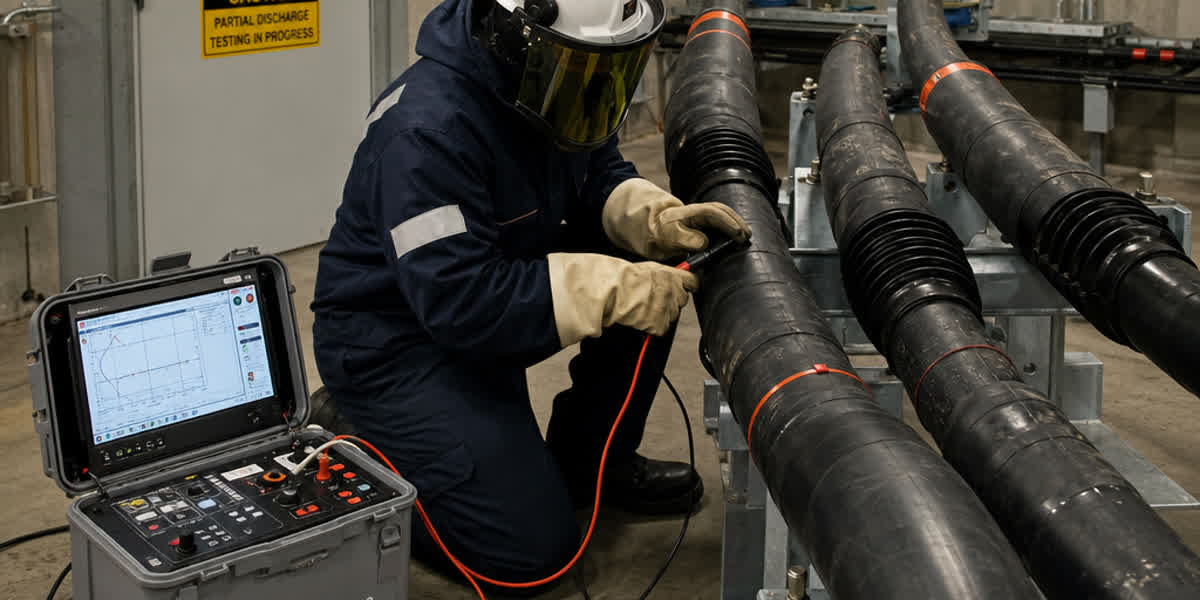
| Línea base térmica | Inspección infrarroja tras el primer día de plena carga; registrar línea base para análisis de tendencia |
Programa de Mantenimiento Rutinario
| Frecuencia | Actividad |
|---|---|
| Mensual (primer año) | Imagen térmica de todos los empalmes y anclajes tras carga máxima |
| Trimestral | Patrulla aérea: desorganización de capas, abrasión, objetos extraños, varillas dañadas |
| Semestral | Medición de flecha a temperatura conocida; tendencia frente a línea base |
| Anual | Inspección infrarroja de toda la línea; comprobar estado y espaciamiento de amortiguadores |
| 3 años | Muestreo de par de apriete; inspeccionar puntos de suspensión por fretting |
| 5 años | Inspección detallada de superficie (oxidación, alambres rotos); verificar estado del alma en vanos representativos |
| 10 años | Evaluación completa de condición; re-verificar modelo de ampacidad contra temperaturas medidas |
💡 Regla de umbral térmico: si cualquier empalme supera en más de 10°C la temperatura de la superficie del conductor a la misma carga, investigar de inmediato — unión de alta resistencia en desarrollo. Más de 20°C de diferencia = programar corte y re-terminal.
Resolución de Problemas Comunes
| Problema | Causa probable | Solución |
|---|---|---|
| Flecha mayor que la de diseño tras el asentamiento | Margen KCM subestimado | Recalcular con modelo de solo alma; ajustar tensión en el próximo corte |
| Desorganización de capas durante el tendido | Tensión excesiva o poleas pequeñas | Detener la tracción; inspeccionar; empalmar la sección dañada |
| Empalme caliente (ΔT >10°C) | Presión de engarce incorrecta o matriz equivocada | Re-terminal con matriz correcta; verificar con microóhmetro |
| Daño por vibración en la grapa | Amortiguadores ausentes/pequeños, espaciado incorrecto | Instalar según estudio IEEE 664; reparar el conductor |
| Rotura de alambres de aluminio en el anclaje | Fatiga por flexión del aluminio blando | Añadir varillas de armadura; usar anclaje de mayor radio |
| Corrosión del alma de acero | Daño del recubrimiento en servicio costero/industrial | Especificar alma aluminizada o galvanizado Clase C; aplicar manguitos de reparación |
| Abrasión del aluminio recocido | Residuos en gargantas de polea o contacto con cable de acero | Inspeccionar equipos antes del tendido; usar piloto sintético |
| Ruido de corona/RI por encima del límite | Bordes afilados de herrajes o alambres dañados | Alisar herrajes, sustituir alambres dañados, re-comprobar CISPR 18-2 |
Consideraciones de Seguridad
| Peligro | Precaucion |
|---|---|
| Tensión inducida en línea desenergizada | Poner a tierra ambos lados de la zona de trabajo; conjuntos portátiles; tratar como en tensión hasta el conexionado |
| Alta tracción de tendido | Mantenerse fuera de la línea de fuego; equipos clasificados; máximo 20% RTS |
| Caídas durante el engrape | Protección anticaídas integral; plataformas de trabajo en puntos de suspensión |
| Ciclo térmico KCM | La superficie alcanza 200°C — no tocar; alertar al personal; coordinar con el despacho |
| Proximidad a líneas en tensión | Mantener distancias de aproximación según normativa local (p. ej., 3,7 m para 230 kV) |
| Fragilidad del aluminio recocido por debajo de –10°C | Aplazar el trabajo o precalentar; no doblar por debajo de la temperatura mínima |
Preguntas Frecuentes (FAQ)
P1: ¿Pueden reutilizarse los herrajes ACSR existentes para ACSS?
No. Los anclajes, empalmes y grapas de suspensión ACSR estándar suelen estar clasificados para 90°C–100°C continuos. El ACSS exige herrajes clasificados 200°C+ para operación continua y 250°C para emergencia. Reutilizar herrajes de 90°C en un conductor de 200°C crea un punto de fallo garantizado. Presupueste la sustitución de todos los herrajes de compresión; torres y aisladores normalmente son reutilizables.
P2: ¿Qué es el asentamiento de rodilla y daña la línea?
La rodilla es la temperatura (≈80°C–100°C) a la que el aluminio recocido empieza a relajarse plásticamente en lugar de elásticamente. Durante el primer calentamiento por encima de 175°C, el aluminio transfiere permanentemente su parte de tensión al alma de acero, causando un aumento único de flecha. Es un comportamiento diseñado y predecible, no un daño. Gestionado correctamente (sobre-tensión, dos fases o margen de diseño), la línea alcanza su flecha final y permanece estable en todos los ciclos térmicos posteriores.
P3: ¿Cuál es la tracción máxima de tendido del ACSS?
Tirar a no más del 20% de la RTS, con tensión inicial de tendido al 15%–25% de la tensión final de diseño. El aluminio recocido tiene solo el 50%–60% de la resistencia a tracción del alambre estirado en frío, por lo que sobre-tirar causa desorganización de capas y daños. Use dinamómetro en cada tendido.
P4: ¿Por qué el ACSS necesita herrajes de 200°C si el ACSR opera a 90°C?
El ACSS está diseñado para operar a 200°C continuos y 250°C de emergencia. Cada componente del camino de corriente — anclajes, empalmes, puentes y sus conectores — debe tener clasificación térmica equivalente; de lo contrario el herraje se convierte en el cuello de botella y falla mientras el conductor sigue sano. Los herrajes de alta temperatura suelen usar aleaciones de aluminio-circonio o cuerpos de acero especialmente diseñados.
P5: ¿En qué se diferencia el mantenimiento del ACSS del ACSR?
Tres diferencias dominan: (1) la imagen térmica es una herramienta de primera línea — empalmes y anclajes deben inspeccionarse mensualmente el primer año; (2) la gestión de vibración importa más en los puntos de fijación porque el aluminio recocido es más sensible a la fatiga, por lo que amortiguadores y varillas de armadura son obligatorios, no opcionales; (3) tras el asentamiento inicial, la flecha es notablemente estable — un cambio de flecha en servicio suele indicar un problema real (alambre roto, grapa deslizada) en lugar de fluencia normal, así que investigue en lugar de re-tensar.
P6: ¿Puede instalarse ACSS en torres ACSR existentes sin modificación?
En casi todos los casos, sí — es la propuesta de valor central. El ACSS usa los mismos nombres clave, por lo que diámetro exterior, peso y RTS coinciden con el ACSR que sustituye. Verifique en diseño cadenas de aisladores, estructuras de anclaje y cimentaciones; solo los herrajes (grapas, anclajes, empalmes) deben actualizarse a clasificación de alta temperatura. Para líneas de AAAC o de aluminio puro AAC, la verificación de torres sigue siendo necesaria porque las cargas mecánicas difieren.
P7: ¿Cuánto dura una línea ACSS?
30–40 años en operación normal ≤200°C. Como el aluminio ya está totalmente recocido, no se produce más ablandamiento en servicio; los mecanismos de envejecimiento dominantes son la oxidación y la corrosión del alma de acero. En entornos costeros o industriales, especifique alma aluminizada o galvanizado Clase C para proteger el alma a temperatura elevada.
P8: ¿Cuándo debe hacerse el ciclo de asentamiento, inmediatamente o más tarde?
Inmediatamente, a los pocos días del tendido, mientras la línea es accesible y antes de ponerla en pleno servicio. Retrasar el asentamiento significa que el aumento permanente de flecha ocurre bajo carga en un momento no controlado (a menudo durante la primera ola de calor). Un calentamiento controlado de 1–2 horas a 200°C con flecha monitorizada convierte la incertidumbre en una condición final conocida.
Referencias y Normas
| Norma | Descripción |
|---|---|
| ASTM B857 | Conductores de aluminio cableados concéntricamente con alma de acero recubierta (ACSS) — norma principal del producto |
| ASTM B802/B498 | Requisitos del alambre de alma de acero galvanizado |
| ASTM B609 | Alambre de aluminio 1350, recocido (templado O) |
| IEC 61089 | Conductores eléctricos aéreos de hilos redondos cableados concéntricamente |
| IEEE 524 | Instalación de conductores de líneas aéreas de transmisión (Cap. 15: ACSS) |
| IEEE 738 | Relación corriente-temperatura de conductores aéreos desnudos |
| IEEE 664 | Vibración acústica / aplicación de amortiguadores |
| IEEE 1185 | Límites de presión lateral |
| IEC 61395 | Procedimientos de ensayo de fluencia para conductores cableados |
| IEC 61238-1 | Conectores de compresión (Clase A, 210°C) |
| CIGRE TB 244 | Comportamiento térmico de conductores aéreos |
| CIGRE TB 324 | Métodos de cálculo flecha-tensión |
| CISPR 18-2 | Límites de interferencia de radio para líneas aéreas |
Conclusión
La instalación de ACSS no es difícil — es distinta. Las tres reglas que mantienen un proyecto a tiempo y en flecha son: tender suave (≤20% RTS, poleas de 25× el diámetro), asentar pronto (ciclo controlado a 200°C en los primeros días) e inspeccionar térmicamente (vigilancia mensual de empalmes el primer año). Todo lo demás sigue la práctica estándar de líneas aéreas, que es precisamente la razón por la que el ACSS sigue siendo la opción HTLS más rentable para los programas mundiales de re-potenciación de redes.
Zhengzhou Sitong Cable fabrica conductores ACSS y ACSS/TW según ASTM B857, IEC 61089 e IEEE 524, con soporte integral de proyecto, desde cálculo de ampacidad hasta supervisión en campo. Para estudios flecha-tensión específicos, selección de herrajes o una cotización, contacte con nuestro equipo de ingeniería.
👉 Explore nuestra gama de conductores ACSR 👉 Guía Técnica Completa del Conductor ACSS: Normas, Especificaciones y Selección 👉 Contacte con nuestro equipo
📬 Consultas de ventas: sales@sitongcable.com | 📞 Teléfono: +86-371-69176007
Esta guía fue preparada por el equipo de ingeniería de SiTong Cable. Todos los datos técnicos referencian ASTM B857, IEC 61089, IEEE 524, IEEE 738 y CIGRE TB 244/324.