Low Voltage Aerial Bundled Cable (LV ABC) Hardware and Insulation Piercing Connectors (IPC): Technical Guide to EN 50483 and NFC 33-020 Standards, Shear-Nut Torque Control and Bimetallic Connection Engineering
Low Voltage Aerial Bundled Cable (LV ABC) Hardware and Insulation Piercing Connectors (IPC): Technical Guide to EN 50483 and NFC 33-020 Standards, Shear-Nut Torque Control and Bimetallic Connection Engineering
This comprehensive technical guide provides electrical engineers and utility contractors with an in-depth analysis of low-voltage aerial bundled cable (LV ABC) hardware, insulation piercing connectors (IPC), shear-head torque control mechanisms, bimetallic corrosion prevention, and qualification testing under EN 50483 and NFC 33-020 standards.
1. Introduction: The Critical Role of Hardware in Overhead ABC Systems
Overhead low-voltage distribution networks have experienced a paradigm shift over the past four decades, transitioning from traditional bare open-wire lines to insulated aerial bundled cable (ABC) systems. While XLPE and HDPE insulated phase conductors eliminate phase-to-phase short circuits caused by clashing conductors, tree contact, and wildlife interference, the overall reliability, electrical efficiency, and operational lifespan of an LV ABC network are governed by its interface hardware.
Field diagnostic data from power utilities across Latin America, Africa, and Southeast Asia demonstrates that over 75% of overhead secondary distribution outages are attributable not to primary cable dielectric breakdown, but to joint, connector, and dead-end hardware degradation. Poor electrical contact leads to localized thermal runaway, conductor annealing, insulation melt-through, and intermittent open circuits. Conversely, improper mechanical clamping causes localized stress concentrations, micro-cracking of insulation jackets, and mechanical drop failures during high-wind or ice-loading events.
Modern LV ABC systems are deployed primarily under two topological architectures: 1. Self-Supporting Systems (4-Core / 2-Core / 3-Core Bundles): Where all phase and neutral conductors share equal mechanical tensile loads, typically utilizing hard-drawn stranded aluminum conductors (AAC). 2. Insulated Neutral Messenger Systems (French Standard / NFC System): Where an insulated, high-strength aluminum alloy messenger—such as an AAAC conductor or an ACSR conductor—carries 100% of the mechanical span tension, while phase conductors are loosely bundled around it.
+----------------------------------------------------------------------------------------------------+
|                               LV ABC SYSTEM TOPOLOGY COMPARISON                                    |
+------------------------------+----------------------------------+----------------------------------+
| Feature                      | Self-Supporting 4-Core System    | Insulated Neutral Messenger System|
+------------------------------+----------------------------------+----------------------------------+
| Mechanical Tension Carrier   | Distributed across all 4 cores   | Exclusively on Neutral Messenger |
| Conductor Material           | Hard-drawn Aluminum (AAC)        | High-Strength Al Alloy (AAAC)    |
| Anchoring Clamp Type         | 4-Core Wedge Dead-End Clamp      | Single Conductor Wedge Clamp     |
| Suspension Clamp Type        | 4-Core Cradle / Roller Clamping  | Single Messenger Suspension Hook |
| Typical Span Length          | 30 m to 45 m                     | 40 m to 70 m                     |
| Vulnerability to Wind Gallop | Moderate                         | Extremely Low                    |
| Applicable Standards         | HD 626, BS 7870, AS/NZS 3560     | NFC 33-020, EN 50483-2/3, IEC    |
+------------------------------+----------------------------------+----------------------------------+
Achieving a 30-to-40-year maintenance-free service life requires precise matching between cable specifications and dedicated pole line fittings and hardware.
2. Anatomical Engineering of Insulation Piercing Connectors (IPC)
The Insulation Piercing Connector (IPC) is the technological cornerstone of modern LV ABC distribution. Unlike traditional split-bolt or compression taps that require stripping the weather-resistant XLPE insulation—exposing stranded conductors to moisture, galvanic attack, and human touch hazards—the IPC establishes robust electrical continuity through the insulation barrier while maintaining complete environmental and dielectric sealing.
                              [ SHEAR-HEAD TORQUE NUT ]
                                        |
                                [ STAINLESS STEEL BOLT ]
                                        |
                            +-----------+-----------+
                            |  TOP HOUSING (PA66)   |
                            +-----------------------+
                            | [ELASTOMERIC GASKET]  |
                            |   /\/\/\/\/\/\  | <-- Piercing Contact Blades
  MAIN CABLE (XLPE) =======>|=======================|<======= Contact Teeth penetrate
                            |   \/\/\/\/\/\/  |     insulation into Al strands
                            | [SILICONE SEALANT]    |
                            +-----------------------+
                            | [ELASTOMERIC GASKET]  |
                            |   /\/\/\/\/\/\  |
  BRANCH TAP (Al/Cu) ======>|=======================|<======= Branch Teeth penetrate
                            +-----------------------+
                            | BOTTOM HOUSING (PA66) |
                            +-----------------------+
2.1 Contact Blade Geometry and Metallurgy
The heart of an IPC consists of conductive tooth plates. For aluminum-to-aluminum (Al-Al) and aluminum-to-copper (Al-Cu) connections, contact blades are engineered from high-conductivity, hot-forged aluminum alloy or high-purity tinned copper: - Pyramidal and Chisel Geometry: Teeth are sharpened to micro-tolerances. When downward torque is applied, the teeth slice cleanly through the resilient cross-linked polyethylene (XLPE) or HDPE insulation without tearing or displacing the underlying stranded wires. - Gas-Tight Contact Zones: The teeth displace the microscopic aluminum oxide ($Al_2O_3$) film naturally present on outer conductor strands, establishing a gas-tight, low-resistance metallic interface.
2.2 Torque-Control Shear-Head Mechanism
Proper electrical contact pressure must be achieved without crushing the stranded conductor cores. Under-torquing leads to high contact resistance and overheating; over-torquing severs individual conductor strands, drastically reducing the ampacity and mechanical pullout strength.
To eliminate human error during field installation, high-grade IPCs utilize a sacrificial dual-hex shear nut engineered from zinc alloy or reinforced polymer: - The installer tightens the outer hexagonal nut with a standard socket wrench. - As the clamping force reaches the engineered threshold (typically $12\text{ to }18\text{ N}\cdot\text{m}$ for service drop taps, and $20\text{ to }45\text{ N}\cdot\text{m}$ for mainline taps), the shear neck fractures cleanly. - The remaining integral lower hex nut remains in place solely for subsequent de-energized dismantling if required.
2.3 Environmental and Water-Tight Sealing
IPCs must maintain hermetic integrity in tropical torrential rain, coastal salt fog, and industrial sulfur environments: - Elastomeric Gaskets: Molded from UV-resistant EPDM or liquid silicone rubber (LSR), the seal envelops the pierced insulation entry points under continuous mechanical compression. - Factory-Injected Hydrophobic Compound: The interior tooth cavity is pre-filled with high-dielectric, non-conductive silicone grease with a dropping point exceeding $180^\circ\text{C}$. This grease displaces residual air, inhibits galvanic oxidation, and blocks capillary water ingress along the stranded core. - Waterproof End Caps: Flexible terminal caps seal the exposed ends of branch service lines or anti-theft concentric cables.
3. Governing International Standards and Qualification Testing
Reliable utility deployment mandates compliance with international performance benchmarks. The two globally recognized standard frameworks governing LV ABC hardware are CENELEC EN 50483 (Parts 1–6) and French NFC 33-020 / NFC 33-003, complemented by IEC 61284 and ANSI C119.4.
+--------------------------------------------------------------------------------------------------------+
|                              EN 50483 HARDWARE STANDARD SERIES MATRIX                                 |
+-------------------+------------------------------------------------------------------------------------+
| Standard Code     | Scope and Component Covered                                                        |
+-------------------+------------------------------------------------------------------------------------+
| EN 50483-1        | General requirements and test conditions for LV ABC accessories                   |
| EN 50483-2        | Tension and suspension clamps for self-supporting aerial bundled cable systems     |
| EN 50483-3        | Tension and suspension clamps for insulated neutral messenger systems (NFC)        |
| EN 50483-4        | Insulation Piercing Connectors (IPC) and terminal connectors                       |
| EN 50483-5        | Electrical aging, thermal endurance, and current cycling testing                  |
| EN 50483-6        | Environmental, corrosion, UV weathering, and climatic aging testing                |
+-------------------+------------------------------------------------------------------------------------+
3.1 Dielectric Immersion Testing (Water Withstand Test)
Per EN 50483-4 and NFC 33-020, IPCs undergo severe waterproof dielectric testing: 1. The connector is assembled on the designated cable sizes at the specified shear torque. 2. The assembly is immersed in a water tank at a depth of $30\text{ cm}$ with a surfactant wetting agent. 3. A test voltage of $6\text{ kV AC}\text{ at }50\text{ Hz}$ is applied between the conductor core and the water bath for $1\text{ minute}$. 4. Pass Criteria: Zero dielectric breakdown or flashover; leakage current must not exceed $0.5\text{ mA}$.
                      6 kV AC HIGH-VOLTAGE TEST RIG (EN 50483-4)
                      +----------------------------------------+
                      |         HV TEST TRANSFORMER            |
                      +-------------------+--------------------+
                                          | (6 kV Probe)
                        ==================|=================== Conductor Core
                       [  IMMERSION TANK  |                  ]
                       [  Water + Wetting | Agent (30 cm)    ]
                       [        +---------+---------+        ]
                       [        |    IPC CONNECTOR  |        ]
                       [        +-------------------+        ]
                       [                                     ]
                       +------------------+------------------+
                                          |
                                     (Grounded Tank)
3.2 Electrical Aging and Thermal Cycling (Class A Connectors)
Under EN 50483-5 and IEC 61284 Class A: - The assembly is subjected to 500 thermal cycles (heating by elevated current to conductor temperature $T_{\text{cond}} = 120^\circ\text{C}$, followed by forced cooling). - Contact resistance ($R_{\text{cont}}$) is monitored throughout. - Criteria: $$\lambda = \frac{R_n - R_0}{R_0} \le 0.15$$ The resistance factor $\lambda$ must not drift by more than 15%, and connector temperature must never exceed the reference conductor temperature ($T_{\text{conn}} \le T_{\text{ref}}$).
3.3 Mechanical Tensile and Environmental Ageing
- Tensile Pullout: Branch conductors must withstand a minimum axial pull force equal to 10% to 25% of conductor rated breaking strength (RBS) without slipping or contact loss.
- Climatic Ageing: Method 1 UV radiation (xenon arc lamp per ISO 4892-2) combined with neutral salt spray (EN 60068-2-11) for 1000 hours to ensure housing polymers resist environmental stress cracking (ESC).
4. Mechanical Suspension and Dead-End Tension Hardware
Securing aerial bundled cables to poles and structures requires dedicated mechanical assemblies that distribute tension without compromising insulation jackets.
                              DEAD-END (ANCHOR) WEDGE CLAMP
                     +---------------------------------------------+
                     |                 ALUMINUM BODY               |
                     |  +-------+                       +-------+  |
  STAINLESS STEEL    |  | WEDGE |======[ABC CABLE]======| WEDGE |  |===>> [POLE BRACKET]
  FLEXIBLE BAIL =====|  +-------+                       +-------+  |
                     |             SELF-TIGHTENING TRACK           |
                     +---------------------------------------------+
4.1 Anchoring / Dead-End Clamps
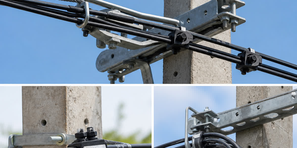
Dead-end clamps are installed at terminal poles, angle poles ($>30^\circ$), and intermediate tensioning stations: - Wedge Clamping Principle: Self-tightening conical wedges fabricated from high-grade fiberglass-reinforced polyamide (PA66-GF30) grip the cable bundle or neutral messenger. As line tension ($T$) increases, the wedges draw deeper into the aluminum alloy housing, increasing radial clamping pressure proportionally ($F_{\text{clamp}} \propto T$). - Insulation Protection: The wedge contact surfaces feature smooth, rounded tooth profiles that prevent point-load cutting into the XLPE jacket even at maximum design working tensions ($>15\text{ to }25\text{ kN}$). - Stainless Steel Bail: A flexible, corrosion-resistant stainless steel (AISI 304 or 316) wire bail connects the clamp body to pole brackets and eye hooks, accommodating wind sway and line vibration.
4.2 Suspension Clamps and Movable Links
Intermediate tangent poles ($0^\circ\text{ to }30^\circ\text{ line angle}$) utilize suspension assemblies: - Sacrificial Weak-Link System: In insulated neutral messenger systems, the suspension clamp incorporates a calibrated mechanical fuse (typically breaking at $4\text{ to }6\text{ kN}$). If a falling tree branch strikes the span, the suspension link shears cleanly, dropping the bundle to the ground without pulling down the utility poles. - Low-Friction Sleeve: Neoprene or elastomeric inserts cushion the bundle, dampening high-frequency aeolian vibrations and preventing mechanical fretting wear against pole brackets.
5. Bimetallic Transition Engineering and Connection Interfaces
Connecting aluminum overhead cables to copper substation bushings, circuit breakers, or service entrance panels presents severe galvanic corrosion hazards. The standard electrode potential difference between aluminum ($-1.66\text{ V}$) and copper ($+0.34\text{ V}$) generates a driving potential of $2.00\text{ V}$. In the presence of moisture and electrolyte (salt or industrial pollutants), aluminum acts as a sacrificial anode and rapidly oxidizes into non-conductive aluminum hydroxide ($Al(OH)_3$).
                         GALVANIC CORROSION CELL (UNPROTECTED)
                          Electrolyte Film (Rain/Salt Spray)
                         +-----------------------------------+
                         |      e- --->                      |
      ALUMINUM ANODE     |   Al -> Al3+ + 3e-                |    COPPER CATHODE
    (-1.66 V Potential)  |   (Rapid Metal Loss / Pitting)    |  (+0.34 V Potential)
     [ Al Conductor ] ===+                                   +=== [ Cu Conductor ]
                         |   High Contact Resistance (R)     |
                         |   ==> Overheating and Fire Hazard |
                         +-----------------------------------+
5.1 Mitigation via Friction-Welded Bimetallic Lugs
To establish permanent terminations at transformers, switchgear, and meter bases, engineers specify friction-welded bimetallic cable lugs and shear bolt terminals: - Solid-State Friction Welding: The aluminum barrel and copper palm are joined under high-pressure rotational friction. This molecular-level fusion completely eliminates oxygen voids, brittle intermetallic compounds ($CuAl_2$), and internal galvanic interfaces. - Internal Pre-Greasing: The aluminum barrel is pre-charged with synthetic antioxidant paste containing suspended zinc particles to break surface oxide during crimping.
5.2 Transitioning to Other Overhead Conductors
When tying an LV ABC network into existing bare feeder lines—such as an ACAR conductor or galvanized steel strand stay wire—specialized bi-material parallel groove (PG) clamps or dual-rated transition IPCs must be specified to maintain galvanic isolation.
6. Comprehensive Selection and Specification Matrices
Table 1: Standard IPC Sizing Matrix for Overhead Distribution
+------------------+-----------------------+-----------------------+---------------------+-------------------+
| IPC Model Code   | Main Conductor (mm²)  | Branch Tap (mm²)      | Shear Torque (N·m)  | Rated Current (A) |
+------------------+-----------------------+-----------------------+---------------------+-------------------+
| IPC-M1/T1        | 16 – 95 (Al/Cu)       | 1.5 – 10 (Al/Cu)      | 11 ± 1              | 75 A              |
| IPC-M2/T1        | 25 – 150 (Al)         | 6 – 35 (Al/Cu)        | 14 ± 1              | 140 A             |
| IPC-M3/T2        | 35 – 95 (Al)          | 35 – 95 (Al)          | 18 ± 2              | 230 A             |
| IPC-M4/T3        | 50 – 150 (Al)         | 50 – 150 (Al)         | 24 ± 2              | 350 A             |
| IPC-M5/T4 (HV)   | 70 – 240 (Al)         | 70 – 240 (Al)         | 42 ± 3              | 520 A             |
+------------------+-----------------------+-----------------------+---------------------+-------------------+
Table 2: Tension and Suspension Hardware Mechanical Performance Matrix
+---------------------------+-------------------+---------------------+--------------------+--------------------+
| Hardware Component        | Target System     | Applicable Standard | Min. Slip Load     | Min. Tensile UTS   |
+---------------------------+-------------------+---------------------+--------------------+--------------------+
| 4-Core Anchor Clamp       | 4x25 to 4x50 mm²  | EN 50483-2          | 95% Cable RTS      | 15.0 kN            |
| 4-Core Anchor Clamp       | 4x70 to 4x120 mm² | EN 50483-2          | 95% Cable RTS      | 25.0 kN            |
| Neutral Messenger Anchor  | 50 – 70 mm² AAAC  | EN 50483-3 / NFC    | 95% Messenger RTS  | 18.0 kN            |
| 4-Core Suspension Clamp   | 4x25 to 4x120 mm² | EN 50483-2          | No Slippage at 3kN | 12.0 kN            |
| Messenger Suspension Hook | 50 – 70 mm² AAAC  | EN 50483-3 / NFC    | Calibrated Fuse    | 4.5 kN (Fuse Blow) |
+---------------------------+-------------------+---------------------+--------------------+--------------------+
7. Step-by-Step Field Installation Protocol and Failure Mitigation
Proper field installation practices ensure that laboratory performance translates into multi-decade line reliability.
                      STEP-BY-STEP IPC INSTALLATION SEQUENCE
  +-------------------------------------------------------------------------------+
  | STEP 1: Conductor Inspection & Alignment                                      |
  | - Clean cable surface; ensure cable is straight with no axial twisting.       |
  +-------------------------------------------------------------------------------+
                                         |
                                         v
  +-------------------------------------------------------------------------------+
  | STEP 2: Branch End Protection                                                 |
  | - Insert waterproof elastomeric end-cap over exposed branch conductor end.   |
  +-------------------------------------------------------------------------------+
                                         |
                                         v
  +-------------------------------------------------------------------------------+
  | STEP 3: Connector Positioning                                                 |
  | - Slide main and tap conductors fully into designated guide channels.         |
  +-------------------------------------------------------------------------------+
                                         |
                                         v
  +-------------------------------------------------------------------------------+
  | STEP 4: Live-Line Tightening                                                  |
  | - Tighten shear-head hex nut using an insulated socket wrench (No impact guns)|
  +-------------------------------------------------------------------------------+
                                         |
                                         v
  +-------------------------------------------------------------------------------+
  | STEP 5: Shear-Neck Separation                                                 |
  | - Continue smooth rotation until shear nut snaps cleanly. DO NOT RE-TIGHTEN!  |
  +-------------------------------------------------------------------------------+
Critical Field Precautions and Pitfalls:
- Never Use Impact Wrenches: High-frequency torque pulses cause premature shear head fracture before teeth fully penetrate the conductor strands, resulting in high contact resistance.
- Never Strip Insulation for IPCs: Stripping defeats the elastomeric seal and creates void pockets for water accumulation.
- Always Form Drip Loops: Service drop branches must exit downward with a defined drip loop to prevent water from running along the insulation directly into the connector throat.
- Do Not Re-Use Torqued IPCs: Once a shear nut has snapped and teeth have penetrated, the elastomeric gasket and teeth have taken a permanent mechanical set. Re-using an IPC on another cable compromises dielectric and waterproof integrity.
8. Quality Assurance and Manufacturing Excellence at SiTong Cable
As a premier global wire and cable manufacturer founded in 2010, Zhengzhou Sitong Cable Co., Ltd. (SiTong Cable / 郑州四通电缆有限公司) delivers fully integrated, turnkey overhead distribution solutions encompassing both precision-manufactured cables and certified pole line hardware.
+----------------------------------------------------------------------------------------------------+
|                         SITONG CABLE INTEGRATED QUALITY ASSURANCE                                  |
+--------------------------+-------------------------------------------------------------------------+
| Quality Pillar           | Engineering Implementation & Verification                               |
+--------------------------+-------------------------------------------------------------------------+
| Raw Material Purity      | 99.7% virgin electrical-grade aluminum (E.C. grade rod); UV-grade XLPE  |
| Continuous Extrusion     | Automated triple-layer co-extrusion with dry-curing laser concentricity |
| Mechanical Hardware QA   | ISO 9001 certified forging, zinc alloy casting, and PA66-GF30 molding   |
| Electrical Test Lab      | 6 kV underwater dielectric immersion tanks, 1000-cycle heat run benches |
| International Compliance | Full compliance with IEC, EN 50483, NFC 33-020, BS, ASTM & AS/NZS       |
| Export Track Record      | Supplied to national electric utilities in 80+ countries across 5 continents|
+--------------------------+-------------------------------------------------------------------------+
By engineering cables and hardware as an interdependent system, SiTong Cable ensures maximum mechanical compatibility, eliminating line slippage, thermal degradation, and premature connection failures.
9. Frequently Asked Questions (FAQ)
Q1: Can Insulation Piercing Connectors (IPC) be installed on energized lines?
Yes. Modern IPCs meeting EN 50483-4 and NFC 33-020 are specifically engineered for live-line installation. The outer plastic casing, shear-head nut, and tightening bolt are fully insulated from the internal contact blades, providing dielectric isolation exceeding $6\text{ kV AC}$. Linemen must utilize standard insulated tools, personal protective equipment (PPE), and maintain proper line clearance protocols.
Q2: What is the primary difference between EN 50483 and NFC 33-020 testing standards?
While both standards share similar testing methodologies originating from European distribution practices, EN 50483 represents the harmonized CENELEC European Standard with explicit electrical aging classes (Class A for general distribution, Class B for non-critical circuits) and detailed UV weathering regimes. NFC 33-020 is the French national standard specifically tailored for insulated neutral messenger systems with strict water tightness tests ($6\text{ kV}\text{ for }1\text{ min}$). Products engineered by SiTong Cable are type-tested to meet and exceed both standards simultaneously.
Q3: Why does aluminum-to-copper tap connection require special IPC consideration?
Direct contact between bare aluminum and bare copper causes severe galvanic corrosion due to their $2.00\text{ V}$ potential differential. High-performance bimetallic IPCs utilize tinned copper or tin-plated brass contact blades enveloped in antioxidant hydrophobic grease. The heavy tin plating acts as a sacrificial barrier material, preventing the direct galvanic coupling of copper and aluminum while inhibiting moisture ingress.
Q4: How does a wedge dead-end clamp prevent damaging the cable insulation?
Wedge dead-end clamps utilize long, high-grade polyamide (PA66-GF30) wedges designed with a calculated taper angle and broad contact surface. The radial clamping force is distributed evenly along a $150\text{ mm to }250\text{ mm}$ length of the cable bundle. This eliminates localized shear stresses and ensures that the radial pressure remains well below the yield point of the cross-linked polyethylene (XLPE) jacket.
Q5: Can an IPC be re-torqued if a line modification is required?
No. After the sacrificial shear nut snaps, the connector has reached its calibrated depth and contact pressure. If the connection is dismantled, the tooth blades will have blunted and the internal silicone sealant will have been displaced. A brand-new IPC must be installed whenever a line is modified or re-tapped to guarantee long-term reliability and waterproof performance.
10. Conclusion and Technical Support
The mechanical and electrical hardware of an aerial bundled cable network is just as vital as the conductor cores. Specifying fully type-tested insulation piercing connectors, torque-calibrated shear nuts, and durable wedge anchor clamps prevents costly power interruptions, reduces line losses, and guarantees over 30 years of safe grid operation.
👉 Browse our complete Aerial Bundled Cable (ABC) product range
👉 Explore our Pole Line Fittings & Hardware accessories
👉 View our Bimetallic Cable Lugs & Terminals
👉 Contact SiTong Cable Engineering & Sales Team
📬 Sales inquiries: sales@sitongcable.com | 📞 Phone: +86-371-69176007