Instalación y Mantenimiento de Tree Wire / Cable de Separadores: Guía de Campo Completa para Redes de Distribución Aérea
Instalación y Mantenimiento de Tree Wire / Cable de Separadores: Guía de Campo Completa para Redes de Distribución Aérea
El Tree Wire (conductor recubierto) y los sistemas de cable de separadores son la solución probada contra los apagones por vegetación, las faltas por fauna silvestre y las limitaciones de servidumbre de paso en líneas de distribución aérea de media tensión. Esta guía de campo cubre el flujo de trabajo completo de instalación y mantenimiento — desde recepción y almacenamiento hasta tendido, colocación de separadores, pruebas y un programa de inspección de por vida — escrita para ingenieros de distribución, cuadrillas de construcción de líneas y gestores de mantenimiento de empresas de servicios públicos.
Introducción
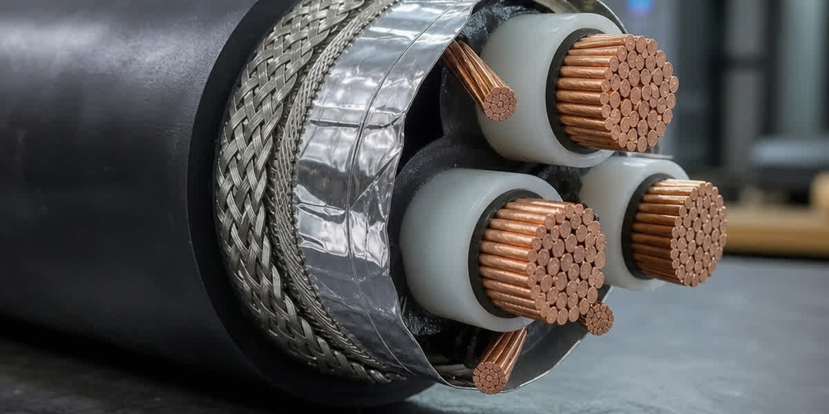
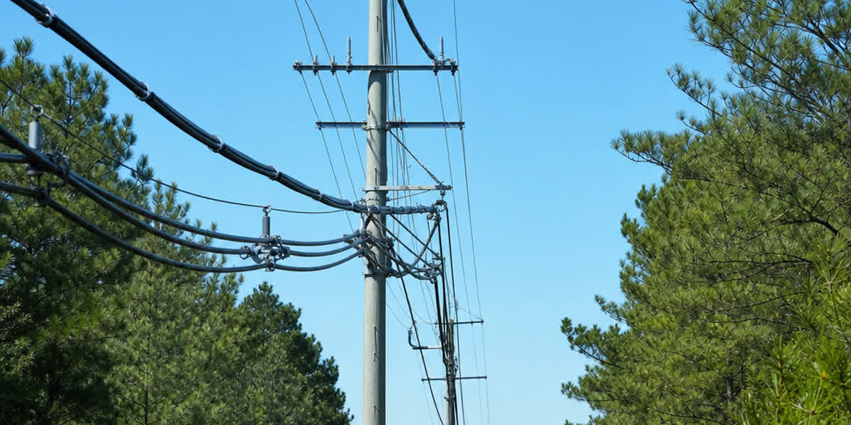
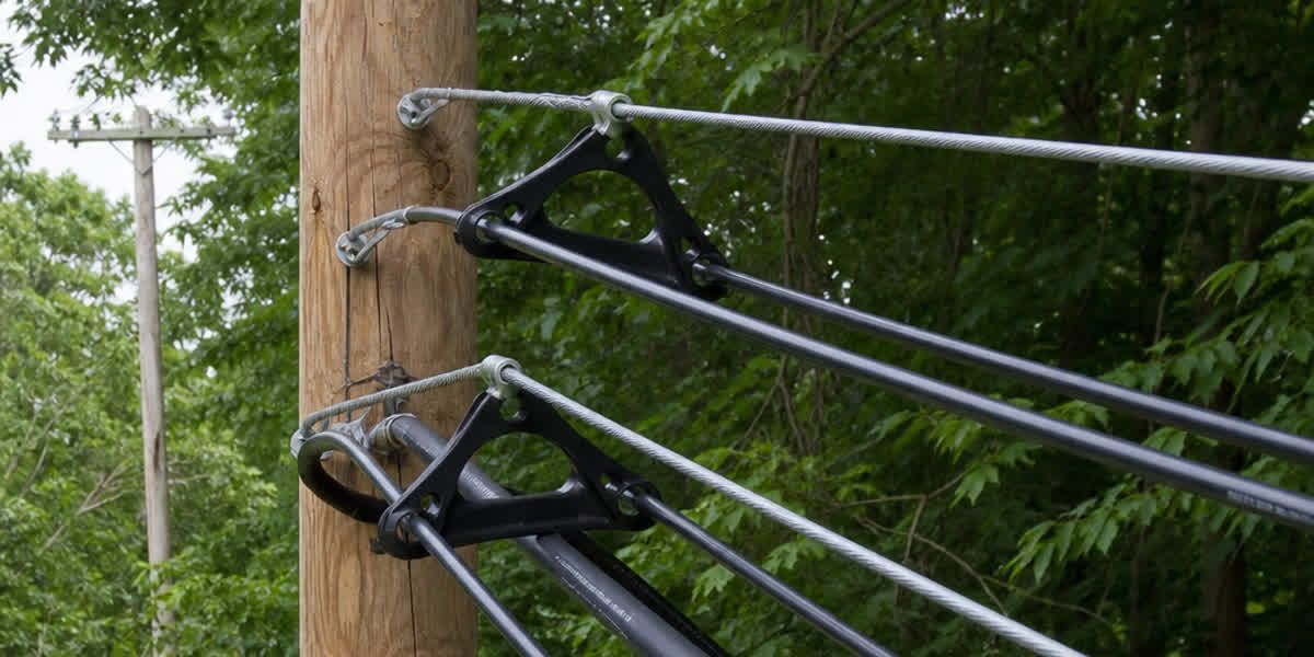
El contacto con vegetación es la mayor causa única de apagones en las redes de distribución aéreas: en muchas empresas representa el 30–60% de todas las interrupciones momentáneas. El Tree Wire resuelve este problema con una capa de aislamiento extruido resistente a la intemperie (típicamente 2–4 mm de XLPE, HDPE o EPR) sobre un conductor cableado convencional, que evita el arco eléctrico durante el contacto temporal con ramas o animales. El cable de separadores lleva el concepto más lejos: dispone tres conductores de fase recubiertos en configuración triangular alrededor de un mensajero de acero galvanizado, separados por separadores aislantes a intervalos regulares.
La economía es convincente. En comparación con las líneas aéreas desnudas, un sistema de Tree Wire puede reducir la servidumbre de paso de 10–30 m a solo 3–8 m, disminuir la frecuencia de poda de árboles hasta un 70% y mejorar las métricas de fiabilidad SAIFI en un 60–80%. En comparación con el cable subterráneo, suele costar un 40–60% menos y es mucho más rápido de reparar. Pero estos beneficios solo se materializan cuando el sistema se instala correctamente: una tensión de tendido incorrecta, un espaciado de separadores erróneo o un aislamiento dañado durante el tendido comprometerán la misma fiabilidad que se busca al comprar el producto.
Esta guía es el complemento de campo de nuestra Guía Técnica Completa de Tree Wire / Cable de Separadores, que cubre normas, especificaciones y selección en profundidad. Aquí nos centramos en la ejecución práctica, con referencia a IEEE 1217, IEEE 524, ICEA S-70-547, IEC 60502-2, IEC 62230, ASTM B230/B231 y NESC C2.
Preparación Previa a la Instalación
Recepción y Almacenamiento
| Elemento de inspección | Criterio de aceptación |
|---|---|
| Estado del carrete | Sin tablones rotos ni daños por impacto; girar sobre su eje, nunca acostado |
| Superficie del aislamiento | Sin cortes, abrasiones ni marcas profundas que atraviesen el recubrimiento |
| Extremos del conductor | Ambos extremos sellados contra la entrada de humedad |
| Herrajes de separadores | Cantidad y tipo conforme a la lista de materiales; sin cuerpos agrietados |
| Documentación | Certificado de prueba de fábrica con tamaño del conductor, espesor de aislamiento y registro de prueba de chispa según IEC 62230 |
Reglas de almacenamiento: Almacenar los carretes en posición vertical sobre una superficie firme y drenada. Proteger el aislamiento de la radiación UV directa durante periodos prolongados — los recubrimientos de polietileno se degradan bajo luz solar sostenida, por lo que se debe almacenar bajo cubierta o sombra si el proyecto se retrasa más de 6 meses. Mantener alejado de fuentes de calor; el recubrimiento no debe superar 50°C durante el almacenamiento. En la recepción, verificar el espesor del aislamiento con un micrómetro contra la hoja de datos (valores típicos: 2,3–4,5 mm según la clase de tensión).
Lista de Verificación de Herramientas y Equipos
| Categoría de herramienta | Elementos | Nota de aplicación |
|---|---|---|
| Tendido | Mordazas para conductor, eslabones giratorios, cuerda de tiro (sintética), gatos para carrete | Usar eslabón giratorio entre cuerda y mordaza para evitar torsión |
| Tendido | Poleas o roldanas, rodillos de tope de poste | Diámetro de polea ≥ 20× diámetro exterior del conductor para proteger el aislamiento |
| Tensado | Frenos o tensionadores, dinamómetro | Mantiene la tensión de tendido dentro de límites |
| Separadores | Herramienta de instalación de separadores, pértiga aislante (si está energizado) | Espaciado de separadores según diseño; ver cálculos abajo |
| Puesta a tierra | Juegos de tierra, cables de conexión | Puesta a tierra del sistema según NESC C2 y práctica de la empresa |
| Medición | Cinta de flecha, tránsito/teodolito, medidor de tensión | Verificación de flecha tras el anclaje |
| Seguridad | Guantes aislantes, cascos, protección anticaídas | El trabajo en líneas energizadas requiere autorización de la empresa |
Plan de Instalación
Preparar un plan escrito que cubra: dirección de tiro y ubicaciones de equipos, longitudes de secciones entre anclajes, protección de cruces (carreteras, ferrocarriles, otras líneas), puntos de anclaje del mensajero, programa de intervalos de separadores y la secuencia de trabajo. Verificar las longitudes de vano y alturas de postes contra los planos de construcción. Confirmar las condiciones meteorológicas — no se debe tender con vientos superiores a 30 km/h ni durante precipitaciones, porque el aislamiento húmedo y el movimiento del conductor aumentan el riesgo de daños.
Cálculos de Ingeniería
Límites de Tensión de Tendido
El aislamiento añade peso y área de viento, pero no contribuye resistencia a la tracción. La tensión de tiro no debe exceder:
- Tensión de tendido: ≤ 20% de la resistencia de rotura nominal (RBS) del conductor, o según especifique el diseño
- Tensión máxima en flecha final: según diseño, típicamente 15–18% de RBS para conductores recubiertos (ligeramente menor que la práctica de conductores desnudos para proteger el recubrimiento)
- Presión lateral en poleas: ≤ 400 kg/m (4 kN/m) para evitar aplastamiento del aislamiento — usar poleas de mayor diámetro o múltiples poleas en posiciones de ángulo pronunciado
Cálculo de Flecha-Tensión
Usar el método estándar de catenaria o parábola con el peso compuesto por unidad de longitud del conductor recubierto (hilos de aluminio/acero + aislamiento). Parámetros clave:
| Parámetro | Valor típico | Notas |
|---|---|---|
| Peso del conductor | +8–15% vs. desnudo (aislamiento) | De la hoja de datos del fabricante |
| Área de viento | +15–25% vs. desnudo | El aislamiento aumenta el área proyectada |
| Módulo inicial | ~60–70 GPa (núcleos AAC/AAAC) | Según métodos de IEEE 524 |
| Elongación térmica | 23×10⁻⁶ /°C (aluminio) | Los conductores recubiertos operan más fríos que los desnudos en contacto con vegetación |
| Carga de hielo | Según código local (p. ej., NESC pesado/medio/ligero) | El aislamiento reduce la adherencia del hielo |
Regla práctica: calcular la flecha con el peso recubierto del conductor, no con el peso del núcleo desnudo. Un aumento de peso del 20% con la misma tensión eleva la flecha aproximadamente un 20% — ignorar el aislamiento es el error de flecha más común en proyectos de Tree Wire.
Espaciado de Separadores
El intervalo de separadores depende del espaciado entre fases, el diámetro del conductor y las fuerzas de cortocircuito. IEEE 1217 proporciona el método de diseño; los valores típicos para sistemas de clase 15 kV son:
| Espaciado entre fases (mm) | Intervalo típico de separadores (m) |
|---|---|
| 150 | 4,5–6 |
| 200 | 6–8 |
| 300 | 8–10 |
Los separadores en medio del vano evitan el choque de conductores bajo galope y condiciones de cortocircuito. Verificar el programa de espaciado contra la clasificación del fabricante de separadores para la corriente de falta del circuito.
Procedimiento de Instalación
Paso 1: Preparación del Sitio
Instalar los soportes de carrete en el extremo de tiro con el carrete girando por la parte superior. Instalar primero el mensajero si el diseño utiliza cable de separadores soportado por mensajero — el mensajero soporta la carga mecánica, por lo que debe tensarse al valor de diseño (típicamente 15–20% de RBS del mensajero) antes de tender los conductores de fase.
Paso 2: Instalar Poleas de Tendido
Colocar roldanas o poleas en cada soporte. Usar poleas con revestimiento liso no metálico clasificadas para conductores recubiertos — los rodillos de acero para conductores desnudos rayarán el aislamiento. Verificar diámetro de polea ≥ 20× diámetro exterior del conductor.
Paso 3: Tender la Cuerda Piloto
Tender una cuerda piloto sintética (nunca cable de acero directamente contra el aislamiento) a través de las poleas, y luego conectar la mordaza del conductor con un eslabón giratorio. Usar una media de tiro o mordaza Kellems sobre el aislamiento, nunca una abrazadera de metal desnudo sobre la superficie recubierta.
Paso 4: Tendido con Tensión
Tirar del conductor a tensión controlada usando el freno del tensionador. Monitorear el dinamómetro continuamente; mantener la tensión ≤ 20% de RBS. Aplicar protección temporal en cada cruce (carretera, ferrocarril, línea de comunicación) según NESC C2 e IEEE 524. Caminar junto a la línea detrás del tiro para verificar enganches y daños al aislamiento.
Paso 5: Flecha y Engrapado
Con el conductor a la tensión y temperatura de diseño, fijar la flecha con instrumento (tránsito o tablero de flecha), nunca a ojo. Anclar el conductor en cada extremo con herrajes de anclaje aprobados y dimensionados para el conductor recubierto — los anclajes de compresión deben instalarse con matrices que coincidan con el diámetro exterior del conductor incluyendo el aislamiento, o con el aislamiento retirado en el punto de terminación según instrucciones del fabricante. Engrapar el conductor en las grapas de suspensión con insertos de amortiguación que protejan el recubrimiento.
Paso 6: Instalar Separadores
Instalar separadores aislantes a los intervalos de diseño usando la herramienta de instalación de separadores. Los separadores deben sujetar sin cortar el aislamiento; verificar el acoplamiento y orientación correctos de cada separador. En configuraciones de cable de separadores, los tres conductores de fase deben mantener el espaciado de fase de diseño en cada posición de separador.
Paso 7: Terminaciones y Conexiones
Retirar el aislamiento según la especificación del fabricante en las terminaciones. Usar conectores clasificados para conductores recubiertos — conectores de compresión para la sección desnuda, con kits de terminación de reducción de aislamiento o control de esfuerzo en las bajadas y conexiones de transformador. Sellar todos los extremos de conductor expuestos con compuesto o tapas aprobados.
Paso 8: Conexión y Puesta a Tierra
Completar la puesta a tierra del sistema según NESC C2: conectar a tierra el mensajero a intervalos especificados (típicamente cada 500 m y en los anclajes), unir el mensajero al sistema de neutro/tierra e instalar pararrayos en los postes de bajada. Verificar la continuidad de puesta a tierra con un óhmetro de baja resistencia antes de la energización.
⚠️ Aviso de seguridad: El aislamiento del Tree Wire está diseñado para protección de contacto momentáneo, NO como sustituto de la distancia de seguridad ni de las prácticas de trabajo seguro. Tratar todos los conductores recubiertos como energizados hasta que se verifique su desenergización y puesta a tierra. Usar herramientas aisladas y métodos de pértiga para trabajo en vivo.
Inspección y Pruebas Posteriores a la Instalación
| Elemento de inspección | Criterio de aceptación |
|---|---|
| Integridad del aislamiento | Sin cortes, abrasiones ni perforaciones visibles en todo el recorrido |
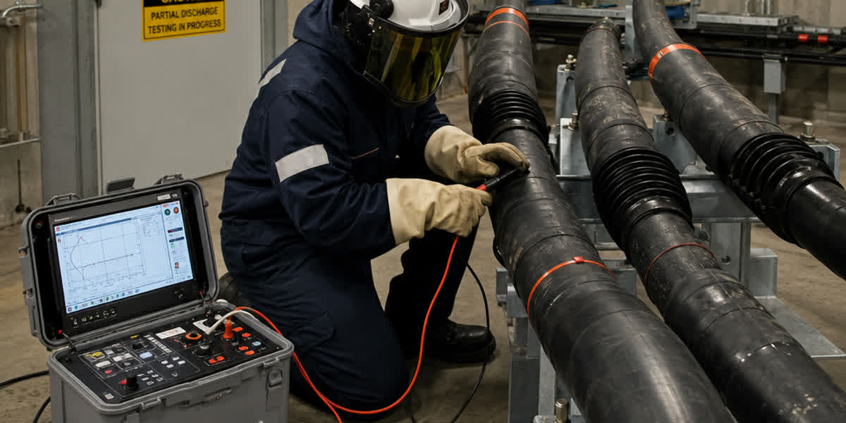
| Prueba de chispa (si aplica) | El aislamiento pasa la prueba de chispa de fábrica según IEC 62230 antes y después de la instalación |
| Verificación de flecha | Dentro de ±5% de la flecha de diseño a temperatura de referencia |
| Colocación de separadores | Intervalos dentro de ±10% del diseño; todos los separadores totalmente acoplados |
| Herrajes de anclaje y empalmes | Instalación correcta, sin piezas sueltas |
| Continuidad de puesta a tierra | < 1 Ω a tierra del sistema en cada punto de puesta a tierra |
| Distancias | Fase-fase y fase-tierra según tablas de NESC C2 |
Antes de la energización, realizar una patrulla visual de la ruta por helicóptero o dron y, cuando la empresa lo requiera, una prueba de resistencia de aislamiento (megóhmetro) — lecturas por debajo de 100 MΩ/km a 1 kV CC justifican investigación.
Programa de Mantenimiento Rutinario
| Frecuencia | Actividad |
|---|---|
| Mensual (primeros 6 meses) | Patrullar vanos críticos; verificar contacto con vegetación y daños a separadores |
| Trimestral | Podar vegetación para mantener distancia mínima; verificar tensión del mensajero |
| Anual | Escaneo infrarrojo de empalmes, anclajes y terminaciones; verificar tendencias de flecha |
| Cada 3 años | Inspección detallada de tope de poste; verificar acoplamiento de separadores; revisar rastreo o daño UV del aislamiento |
| Cada 5 años | Inspección completa de la línea; probar condición del aislamiento por muestreo; verificar continuidad de puesta a tierra |
| Tras tormentas mayores | Patrulla de emergencia; verificar choque de conductores, pérdida de separadores y aislamiento dañado |
Análisis de tendencias: registrar lecturas de flecha y tensión anualmente. Un aumento de flecha superior al 5% respecto a la línea base sin cambio de temperatura indica fluencia del conductor o deslizamiento del anclaje — investigar antes de que se convierta en una violación de distancia.
Solución de Problemas Comunes
| Problema | Causa probable | Solución |
|---|---|---|
| Apagón durante contacto con vegetación | Aislamiento dañado en la instalación (rayado por polea o mordaza) | Patrullar y reparar con kit de empalme/cubierta aprobado |
| Choque de conductores con viento | Espaciado de separadores demasiado amplio o separadores faltantes | Reinstalar separadores a intervalos de diseño |
| Rastreo en la superficie del aislamiento | Contaminación + humedad en recubrimiento envejecido | Limpiar o reemplazar sección; considerar recubrimiento de silicona |
| Flecha demasiado alta | Peso incorrecto en el cálculo (desnudo en vez de recubierto) | Recalcular y re-tensar |
| Flecha excesiva del mensajero | Mensajero sub-tensado en la instalación | Re-tensar mensajero al diseño |
| Agrietamiento del cuerpo del separador | Degradación UV o clasificación incorrecta | Reemplazar con separador estabilizado UV de clasificación correcta |
| Ruido de radio / corona | Bordes afilados de herrajes o aislamiento dañado en terminaciones | Ajustar herrajes; reparar terminación |
Consideraciones de Seguridad
| Peligro | Precaución |
|---|---|
| Tensión inducida | Poner a tierra ambos lados de la sección de trabajo; usar tierras personales |
| Conductores energizados (asumir en vivo) | Verificar desenergización, probar y poner a tierra antes del contacto |
| Caídas desde altura | Protección anticaídas completa; procedimientos de escalera y canasta elevadora |
| Fallas de tensión de tiro | Mantener al personal fuera de la zona de tiro; usar herrajes clasificados |
| Daño al aislamiento durante manipulación | Usar mordazas, poleas y rodillos adecuados; inspeccionar antes de tender |
| Trabajo en líneas energizadas | Solo cuadrillas autorizadas con pértiga; herramientas aisladas clasificadas para la tensión del sistema |
Preguntas Frecuentes
1. ¿Se puede instalar Tree Wire como un conductor ACSR normal? No exactamente. El aislamiento requiere poleas de tendido de mayor diámetro (≥ 20× diámetro exterior), mordazas de tiro sobre el recubrimiento en lugar de abrazaderas de metal desnudo y una tensión de tendido ligeramente menor (≤ 20% de RBS) para evitar daños al aislamiento. El cálculo de flecha debe usar el peso compuesto del conductor recubierto, no el peso del núcleo desnudo.
2. ¿Cuál es el vano máximo para Tree Wire / cable de separadores? Los vanos típicos son de 60–150 m para sistemas de clase 15 kV. Son posibles vanos más largos con conductores y mensajeros mayores, pero los sistemas de cable de separadores generalmente se diseñan para vanos de distribución, no para distancias de transmisión. Verificar los criterios de flecha y choque con el ingeniero de diseño.
3. ¿Con qué frecuencia se debe podar con Tree Wire? Mucho menos que con líneas desnudas — típicamente 3–5 veces menos. Como el aislamiento evita arcos durante el contacto momentáneo, la poda solo es necesaria para prevenir el roce sostenido y mantener las distancias legales. Muchas empresas reportan un 60–80% menos de interrupciones relacionadas con vegetación.
4. ¿Es necesario retirar el aislamiento en cada conexión? Sí. En terminaciones y conexiones, el aislamiento se retira según la especificación del fabricante para que el conector haga contacto metal-metal. Usar kits de terminación aprobados y compuestos selladores para proteger los extremos expuestos.
5. ¿Cómo detecto aislamiento dañado después de la instalación? La patrulla visual (terrestre, helicóptero o dron) es el método principal, complementada con una prueba de resistencia de aislamiento (≥ 100 MΩ/km a 1 kV CC). La prueba de chispa según IEC 62230 se puede aplicar al conductor antes de la instalación y en carretes de fábrica.
6. ¿Cuál es la vida útil de diseño de un sistema Tree Wire? 30–40 años con instalación y mantenimiento adecuados. El aislamiento estabilizado contra UV, la selección correcta de separadores y la gestión rutinaria de vegetación son los principales factores que determinan si el sistema alcanza su vida útil completa.
7. ¿Tree Wire y cable ABC son lo mismo? No. El cable ABC (cable aéreo agrupado) es un cable de baja tensión (< 1 kV) con todas las fases trenzadas alrededor de un mensajero, mientras que el Tree Wire es un conductor recubierto de media tensión (5–69 kV) usado en configuraciones espaciadas. Sirven a diferentes clases de tensión y usan diferentes herrajes.
8. ¿Qué normas aplican a la instalación de Tree Wire? Las normas principales son IEEE 1217 (diseño e instalación de sistemas de cable de separadores), IEEE 524 (instalación de conductores aéreos), ICEA S-70-547 (conductores recubiertos resistentes a la intemperie), IEC 60502-2 (aislamiento extruido de media tensión) y NESC C2 (distancias y seguridad). Las normas regionales incluyen BS 7870-5 / ENA TS 43-92 (Reino Unido) y AS/NZS 3599 (Australia/Nueva Zelanda).
Referencias y Normas
| Norma | Descripción |
|---|---|
| IEEE 1217 | Guía para el Diseño e Instalación de Sistemas de Cable de Separadores |
| IEEE 524 | Guía para la Instalación de Conductores de Líneas de Transmisión Aéreas |
| ICEA S-70-547 | Conductores Recubiertos de Polietileno Resistente a la Intemperie |
| IEC 60502-2 | Cables de Potencia con Aislamiento Extruido para Tensiones Nominales 6–30 kV |
| IEC 62230 | Cables Eléctricos — Método de Prueba de Chispa |
| ASTM B230 / B231 | Alambre / Conductores de Aluminio 1350 |
| NESC (ANSI C2) | Código Nacional de Seguridad Eléctrica — distancias y seguridad |
| BS 7870-5 / ENA TS 43-92 | Normas de conductores recubiertos del Reino Unido |
| AS/NZS 3599 | Sistemas australianos/NZ de cable aéreo agrupado y recubierto |
Acerca de SiTong Cable
SiTong Cable fabrica Tree Wire y cable de separadores según normas internacionales (IEEE, IEC, ASTM, BS), con espesores de aislamiento y construcciones de conductor adaptados a las especificaciones de empresas de servicios públicos de todo el mundo. Nuestro equipo de ingeniería apoya los proyectos desde la selección del conductor hasta la guía de instalación y la resolución de problemas en campo. Para una cotización, hojas de datos técnicas o soporte de instalación, contacte a nuestro equipo.
👉 Explore nuestra gama de productos Tree Wire 👉 Tree Wire / Cable de Separadores: Guía Técnica Completa 👉 Contacte a nuestro equipo
📬 Consultas de ventas: sales@sitongcable.com | 📞 Teléfono: +86-371-69176007
Esta guía fue preparada por el equipo de ingeniería de SiTong Cable. Todos los datos técnicos referencian IEEE 1217, IEEE 524, ICEA S-70-547, IEC 60502-2, IEC 62230, ASTM B230/B231 y NESC C2.