Low Voltage Power Cable (0.6/1kV) Installation & Maintenance: Complete Field Guide for Distribution Networks
Low Voltage Power Cable (0.6/1kV) Installation & Maintenance: Complete Field Guide for Distribution Networks
Low voltage (LV) power cables rated at 0.6/1kV (0.6/1.2kV maximum system voltage) form the operational foundation of municipal electrical grids, industrial manufacturing facilities, commercial complexes, renewable energy collector systems, and infrastructure networks. Whether utilizing copper or aluminum conductors insulated with cross-linked polyethylene (XLPE) or polyvinyl chloride (PVC), and armored with steel wire (SWA), steel tape (STA), or aluminum wire (AWA), proper field installation and rigorous lifecycle maintenance dictate whether a cable system achieves its intended 30-to-40-year design life or suffers premature dielectric breakdown.
This comprehensive field engineering guide provides practicing electrical engineers, project managers, site supervisors, and maintenance technicians with standardized installation protocols, engineering calculations, direct burial and containment guidelines, jointing and termination best practices, post-installation testing criteria, and troubleshooting diagnostics in strict compliance with IEC 60502-1, BS 5467, BS 6724, BS 7671 (IET Wiring Regulations 18th Edition), IEC 60228, IEEE 1185, and NEC Articles 300 & 310.
For technical specifications, standard tables, and core construction details of low voltage conductors, refer to our companion technical guide on Power Cable (Medium Voltage & Low Voltage) Specifications and Standards as well as our Armoured Cable (SWA) Complete Technical Guide.
1. Regulatory Standards and Cable Construction Overview
Low voltage power cables operating at 0.6/1kV are manufactured and specified according to well-defined international and regional standards. Understanding the exact construction layers ensures proper handling during mechanical pulling and containment dressing.
1.1 Key Governing Standards
| Standard | Scope & Application | Key Requirements & Highlights |
|---|---|---|
| IEC 60502-1 | Power cables with extruded insulation (1 kV to 3 kV) | Specifies electrical, mechanical, and material requirements for XLPE, EPR, and PVC insulated cables. |
| BS 5467 | Armoured cables for voltages of 600/1000 V and 1900/3300 V | Heavy-duty XLPE insulated, PVC bedded, Steel Wire Armoured (SWA) or Aluminium Wire Armoured (AWA) cables. |
| BS 6724 | Armoured cables with Low Smoke Zero Halogen (LSZH) | Similar mechanical protection to BS 5467 with LSZH thermoplastic bedding and sheathing for public safety. |
| BS 7671 (IET 18th Ed.) | Requirements for Electrical Installations | Sizing rules, voltage drop limits, fault loop impedance ($Z_s$), earthing methods, and containment installation. |
| IEC 60228 | Conductors of insulated cables | Defines Class 1 (solid), Class 2 (stranded), Class 5 (flexible) conductor dimensions and DC resistance limits. |
| IEC 60332-1 / 60332-3 | Flame propagation tests for electrical cables | Single wire vertical flame test (-1) and bunched cable flame propagation test (-3). |
| IEC 60754-1/-2 & 61034 | Halogen acid gas content and smoke density | Ensures acid gas evolution $<0.5\%$ and light transmittance $\ge 60\%$ under fire conditions for LSZH. |
| NEC Article 300 / 310 | General wiring methods and conductors for general wiring | US electrical installation rules, minimum burial depths, ampacity correction, and conduit sizing. |
1.2 Anatomical Layers of 0.6/1kV Armoured Cable
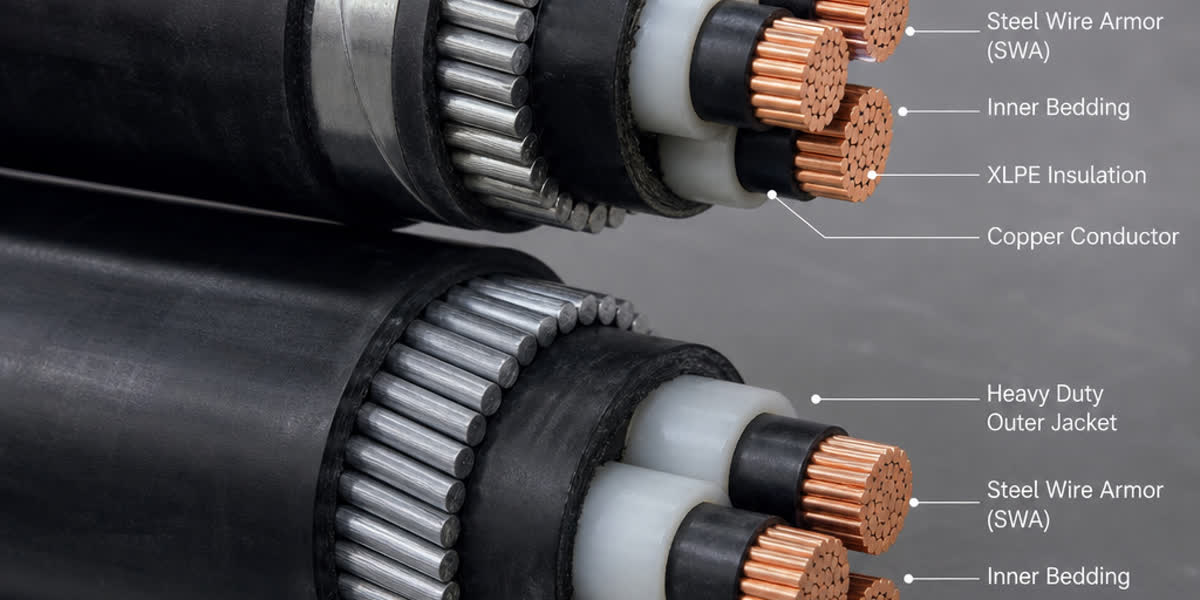
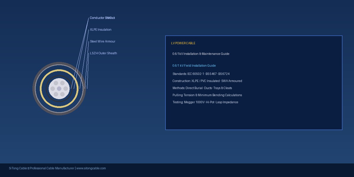
Low voltage armoured cables (e.g., XLPE/SWA/PVC or XLPE/SWA/LSZH) incorporate five structural elements:
- Phase & Neutral Conductors: Plain annealed copper or solid/stranded electrical-grade aluminum complying with IEC 60228. Shaped sector conductors ($3\text{ core}, 3.5\text{ core}, 4\text{ core}$) are commonly used above $50\text{ mm}^2$ to minimize overall diameter and cable weight.
- Dielectric Insulation: Extruded cross-linked polyethylene (XLPE) rated for $90^\circ\text{C}$ continuous conductor temperature ($250^\circ\text{C}$ short-circuit limit for $5\text{ s}$) or Polyvinyl Chloride (PVC) rated for $70^\circ\text{C}$ continuous ($160^\circ\text{C}$ short-circuit).
- Inner Covering / Bedding: Extruded thermoplastic PVC or LSZH compound acting as a protective cushion preventing the metallic armour wires from crushing or penetrating the insulation cores.
- Mechanical Armour:
- Galvanized Steel Wire Armour (SWA): Single layer of circular galvanized steel wires applied helically over multicore cables to provide longitudinal tensile strength and heavy crush/impact protection.
- Aluminium Wire Armour (AWA): Applied exclusively on single-core AC cables to prevent electromagnetic eddy current induction and severe sheath overheating caused by magnetic hysteresis in ferrous steel.
- Steel Tape Armour (STA): Double helical steel tapes for static underground direct burial applications prioritizing rodent resistance over longitudinal tensile pull.
- Outer Protective Sheath (Jacket): High-density PVC (Type ST2 per IEC 60502-1), LSZH thermoplastic (Type ST8), or High-Density Polyethylene (HDPE) offering UV resistance, chemical stability, and water-blocking properties.
2. Pre-Installation Engineering Calculations
Before placing cable drums on site or initiating mechanical pulls, engineering teams must verify pulling tensions, sidewall bearing pressures, bending radii, and installation derating factors.
       ┌─────────────────────────────────────────────────────────┐
       │             PRE-INSTALLATION CALCULATION FLOW           │
       └───────────────────────────┬─────────────────────────────┘
                                   │
         ┌─────────────────────────┴─────────────────────────┐
         ▼                                                   ▼
┌─────────────────────────────────┐         ┌─────────────────────────────────┐
│     MAX PULLING TENSION         │         │     SIDEWALL BEARING PRESSURE   │
│     T = k × A                   │         │     P = T / R                   │
│     • Copper: k = 50 N/mm²      │         │     • Standard limit:           │
│     • Aluminum: k = 30 N/mm²    │         │       P ≤ 730 kg/m (7.2 kN/m)   │
└─────────────────────────────────┘         └─────────────────────────────────┘
                                   │
         ┌─────────────────────────┴─────────────────────────┐
         ▼                                                   ▼
┌─────────────────────────────────┐         ┌─────────────────────────────────┐
│     MINIMUM BENDING RADIUS      │         │     VOLTAGE DROP VERIFICATION   │
│     • Unarmoured: R ≥ 6 × OD    │         │     ΔV = [b(R cosφ + X sinφ)    │
│     • SWA Armoured: R ≥ 8-12× OD│         │          × I × L] / 1000        │
└─────────────────────────────────┘         └─────────────────────────────────┘
2.1 Maximum Permissible Pulling Tension
Exceeding the tensile yield strength of the conductor will cause necking, reduced cross-sectional area, elevated local resistance, and localized hotspots during service.
Formula 1: Pulling by Conductor Pulling Eye
When tension is applied directly to the conductors via a pulling eye: $$T_{\text{max}} = k \times A_{\text{total}}$$ Where: - $T_{\text{max}}$ = Maximum permissible pulling tension (Newtons, $\text{N}$) - $k$ = Permissible conductor tensile stress constant: - Copper conductors: $k = 50\text{ N/mm}^2$ - Aluminum conductors: $k = 30\text{ N/mm}^2$ - $A_{\text{total}}$ = Sum of total phase conductor cross-sectional areas (excluding neutral/earth if smaller, unless pulled simultaneously): - For a $4 \times 185\text{ mm}^2$ copper cable: $A_{\text{total}} = 4 \times 185 = 740\text{ mm}^2$ - $T_{\text{max}} = 50\text{ N/mm}^2 \times 740\text{ mm}^2 = 37,000\text{ N} = 37.0\text{ kN}$ (approx. $3,770\text{ kgf}$)
Formula 2: Pulling by Cable Stocking (Mesh Basket Grip)
When pulling by an external woven wire cable grip over the outer sheath: - For unarmoured cables: $T_{\text{grip}} = 5\text{ N/mm}^2 \times \pi \times D_{\text{cable}} \times L_{\text{grip}}$ (subject to absolute maximum of $5,000\text{ N} / 5.0\text{ kN}$ to prevent outer sheath slip or elongation). - For steel wire armoured (SWA) cables: $T_{\text{grip-SWA}} = k_{\text{armour}} \times A_{\text{armour}}$ ($k_{\text{armour}} = 100\text{ N/mm}^2$ for galvanized steel wire, capped at $15\text{ kN}$ to prevent armour bunching / birdcaging).
2.2 Sidewall Bearing Pressure (SWBP) at Duct Bends
When a cable is pulled around a bend under tension, radial compressive force pushes the cable against the inner bend surface. If this sidewall bearing pressure is excessive, the insulation will be crushed against the conductor or armour.
$$P = \frac{T}{R}$$ Where: - $P$ = Sidewall bearing pressure ($\text{N/m}$ or $\text{kg/m}$) - $T$ = Tension exiting the bend ($\text{N}$) - $R$ = Inside radius of the conduit / bend ($\text{m}$)
Industry Engineering Limits (IEEE 1185 & IEC 60502): - Single-core and multicore unarmoured XLPE/PVC cables: $P_{\text{max}} = 500\text{ kg/m} \approx 4.9\text{ kN/m}$ - Multicore steel wire armoured (SWA) cables: $P_{\text{max}} = 730\text{ kg/m} \approx 7.2\text{ kN/m}$ - Interlocked armoured or steel tape armoured cables: $P_{\text{max}} = 450\text{ kg/m} \approx 4.4\text{ kN/m}$
Example Calculation: A $4 \times 240\text{ mm}^2$ SWA cable pulled around a $90^\circ$ duct bend with radius $R = 1.2\text{ m}$ under an exiting tension of $T = 6,000\text{ N}$: $$P = \frac{6,000\text{ N}}{1.2\text{ m}} = 5,000\text{ N/m} = 5.0\text{ kN/m} \quad (\approx 510\text{ kg/m})$$ Since $5.0\text{ kN/m} < 7.2\text{ kN/m}$, the installation is mathematically safe from sidewall crushing.
2.3 Minimum Bending Radius Specifications
Bending a low voltage cable beyond its elastic deformation limit causes dielectric microrupture, displacement of insulation, and armour wire distortion.
| Cable Type & Construction | Voltage Rating | Minimum Bending Radius during Pulling (Dynamic) | Minimum Bending Radius Installed (Static Fixed) |
|---|---|---|---|
| Single-Core Unarmoured | $0.6/1\text{ kV}$ | $8 \times \text{OD}$ | $6 \times \text{OD}$ |
| Multicore Unarmoured (}\le 25\text{ mm}^2\text{)} | $0.6/1\text{ kV}$ | $6 \times \text{OD}$ | $4 \times \text{OD}$ |
| Multicore Unarmoured (> }25\text{ mm}^2\text{)} | $0.6/1\text{ kV}$ | $8 \times \text{OD}$ | $6 \times \text{OD}$ |
| Single-Core AWA Armoured | $0.6/1\text{ kV}$ | $12 \times \text{OD}$ | $8 \times \text{OD}$ |
| Multicore SWA Armoured | $0.6/1\text{ kV}$ | $10 \times \text{OD}$ | $8 \times \text{OD}$ ($\text{OD} \le 50\text{ mm}$) $10 \times \text{OD}$ ($\text{OD} > 50\text{ mm}$) |
| Steel Tape Armoured (STA) | $0.6/1\text{ kV}$ | $15 \times \text{OD}$ | $12 \times \text{OD}$ |
Note: $\text{OD}$ is the overall outside diameter of the cable.
3. Direct Burial, Ducts, and Containment Guidelines
Low voltage cables can be routed through three primary environments: direct underground burial, underground conduits/ducts, or above-ground cable containment (ladders, trays, and ducts).
   ┌────────────────────────────────────────────────────────┐
   │            DIRECT BURIAL TRENCH PROFILE (BS 7671)      │
   └────────────────────────────────────────────────────────┘
    ▼ Finished Ground Level
    ────────────────────────────────────────────────────────  0 mm
    ░░░░░░░░░░░░ Backfill Soil (Compacted) ░░░░░░░░░░░░░░░░░░
    ════════════════════════════════════════════════════════  300 mm
    [ ⚠️ WARNING TAPE: "CAUTION ELECTRIC CABLE BURIED BELOW" ]
    ░░░░░░░░░░░░ Backfill Soil (Free of Stones) ░░░░░░░░░░░░
    ▓▓▓▓▓▓▓▓▓▓▓▓▓▓▓▓▓▓▓▓▓▓▓▓▓▓▓▓▓▓▓▓▓▓▓▓▓▓▓▓▓▓▓▓▓▓▓▓▓▓▓▓▓▓▓▓  500 mm
    [ PROTECTIVE CONCRETE CABLE TILES / PLASTIC SLABS ]
    ░░░░░░░░░░░░ Stone-Free Washed Sand (75 mm) ░░░░░░░░░░░░
    ▒▒▒▒▒▒▒▒▒▒▒▒▒▒▒▒▒▒▒▒▒▒▒▒▒▒▒▒▒▒▒▒▒▒▒▒▒▒▒▒▒▒▒▒▒▒▒▒▒▒▒▒▒▒▒▒
    ▒▒▒▒   (◉) 0.6/1kV SWA POWER CABLE   (◉)             ▒▒▒▒  600-800 mm
    ▒▒▒▒▒▒▒▒▒▒▒▒▒▒▒▒▒▒▒▒▒▒▒▒▒▒▒▒▒▒▒▒▒▒▒▒▒▒▒▒▒▒▒▒▒▒▒▒▒▒▒▒▒▒▒▒
    ░░░░░░░░░░░░ Stone-Free Washed Sand Bed (75 mm) ░░░░░░░░
    ────────────────────────────────────────────────────────  750-950 mm
    ▼ Trench Bottom (Levelled & Compacted)
3.1 Direct Burial Trench Profile and Specifications
Direct burial of SWA/STA low voltage power cables requires strict adherence to trenching profiles to protect cables from mechanical excavation strikes, settlement subsidence, and thermal stagnation.
- Depth Requirements:
- Non-traffic areas (pedestrian sidewalks, landscaped greenfield): Minimum $600\text{ mm}$ cover to the top of the cable.
- Vehicular crossings (roadways, loading bays, parking lots): Minimum $900\text{ mm}$ cover, with cables encased in heavy-duty smooth-bore HDPE or PVC-U ducts surrounded by concrete encasement (Class C20/25).
- Bedding and Padding:
- Trench bottom must be smoothed, de-watered, and free of sharp rocks, flint, or rubble.
- Lay a minimum $75\text{ mm}$ thick base layer of washed, stone-free quarry sand or fine sifted soil ($<2\text{ mm}$ particle size).
- Place cables with slight intentional lateral snaking ($0.5\%$ to $1.0\%$ excess length) to accommodate thermal expansion/contraction cycles and ground settling.
- Cover cables with another $75\text{ mm}$ to $100\text{ mm}$ layer of sand before placing protective markers.
- Mechanical Protection and Warning Marker:
- Place interlocking heavy-duty polymer cable protection tiles (e.g., Stokbord) or pre-cast concrete cable covers directly above the sand layer.
- Backfill with stone-free excavated soil in $150\text{ mm}$ compacted layers.
- Lay high-visibility yellow or red polyethylene warning tape printed with
"CAUTION: ELECTRIC CABLE BURIED BELOW"at $300\text{ mm}$ depth below finished grade.
3.2 Conduit & Underground Duct Installation
When cables pass through road ducts, building entries, or bridge abutments: - Duct Fill Factor: Total cable cross-sectional area must not exceed $40\%$ of the internal cross-sectional area of the conduit for multiple cables, or $53\%$ for a single cable (NEC Chapter 9, Table 1). - Duct Bellmouths: Fit flared PVC bellmouths or smooth bushings at all duct entry/exit mouths to prevent sheath gouging. - Sealing & Waterstops: Seal all building entry ducts with fire-rated, gas-tight, and water-tight modular transit frames (e.g., Roxtec) or expanding polyurethane duct sealing foam tested to IP68.
3.3 Above-Ground Containment (Trays, Ladders, and Cleats)
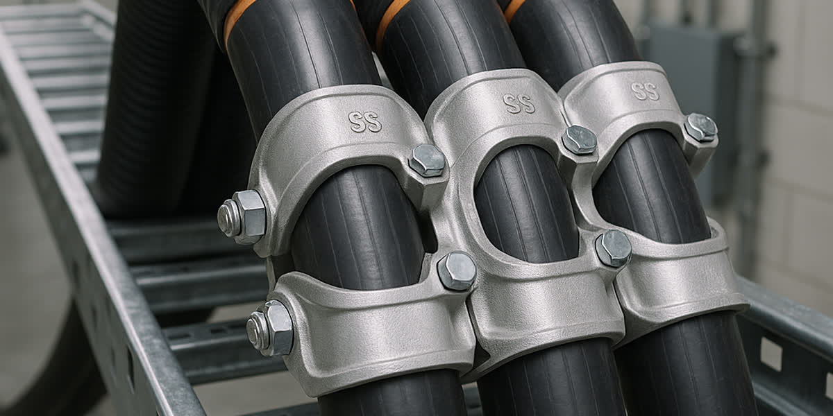
For installations on cable trays, ladders, or structural steelwork: - Horizontal Trefoil Formation: Single-core cables in 3-phase AC circuits must be grouped in trefoil configuration (cloverleaf) and bound using non-magnetic aluminium or polymeric trefoil cleats. - Cleat Spacing per IEC 61914: - Horizontal runs: Maximum $900\text{ mm}$ cleat pitch for multicore; $600\text{ mm}$ for single-core in trefoil. - Vertical runs: Maximum $450\text{ mm}$ to $600\text{ mm}$ spacing to support vertical cable mass. - Intermediate short-circuit straps: Calculated based on available prospective short-circuit fault current ($I_{\text{sc}}$): $$F_{\text{max}} = \frac{0.17 \times I_{\text{peak}}^2}{S}$$ Where $F_{\text{max}}$ is dynamic peak force ($\text{N/m}$), $I_{\text{peak}}$ is peak fault current ($\text{kA}$), and $S$ is center-to-center distance ($\text{m}$).
4. Step-by-Step Installation Procedure
Executing low voltage cable installation on site requires a disciplined 8-step methodology to ensure safety, physical integrity, and compliance.
┌─────────────────────────────────────────────────────────────────────────────────┐
│                    8-STEP FIELD CABLE INSTALLATION WORKFLOW                     │
└─────────────────────────────────────────────────────────────────────────────────┘
  [Step 1]  Route Survey & Trench Preparation
      │
  [Step 2]  Drum Handling, Jack Setup & Pre-Pull Megger Check
      │
  [Step 3]  Cable Pulling, Roller Positioning & Winch Control
      │
  [Step 4]  Bending Radius & Sidewall Pressure Monitoring
      │
  [Step 5]  Containment Dressing, Cleating & BS 6121 Glanding
      │
  [Step 6]  Splicing, Jointing & Termination Procedures
      │
  [Step 7]  Earthing, Armour Bonding & Grounding Verifications
      │
  [Step 8]  Post-Installation Testing, Commissioning & As-Built Logging
Step 1: Pre-Installation Route Survey and Clearance Checks
- Verify the civil trench or containment pathway matches approved AFC (Approved For Construction) shop drawings.
- Ensure minimum clearances from other utilities:
- Gas lines: $\ge 300\text{ mm}$
- Water and sewer mains: $\ge 300\text{ mm}$
- Communication / fiber optic cables: $\ge 300\text{ mm}$ (or physical barrier)
- High voltage power cables ($>1\text{ kV}$): $\ge 500\text{ mm}$
- Install cable rollers along the entire trench route at maximum $2.0\text{ m}$ intervals on straight runs, and specialized triple-corner angled rollers at every directional change.
Step 2: Cable Drum Handling, Inspection, and Positioning
- Inspect the cable drum upon site delivery for transport damage, broken battens, or water ingress at sealed end-caps.
- Confirm drum labeling: cable size, voltage rating ($0.6/1\text{ kV}$), conductor material (Cu/Al), length, and gross weight.
- Mount the drum on hydraulic jacks or a heavy-duty drum trailer capable of supporting the full drum mass. Ensure the axle is perfectly horizontal and secured with safety collar clamps.
- Position the drum so the cable pays off smoothly from the top of the reel, feeding naturally in the direction of the trench without sharp reverse bending.
- Perform a pre-pull Insulation Resistance (Megger) test between cores and armour to ensure no factory/shipping defects exist.
Step 3: Cable Pulling, Roller Spacing, and Tension Control
- Fit a calibrated pulling eye directly to the copper/aluminum conductors or install an appropriate wire mesh basket grip over the armour with double-banded stainless steel clamps.
- Attach a heavy-duty ball-bearing swivel between the pulling winch wire and the cable pulling eye to relieve torsional twisting during pulling.
- Apply water-based, non-staining, polymer cable pulling lubricant (e.g., Polywater) at the feeding tube and all conduit entry points. Lubricant reduces friction coefficient ($\mu$) from $0.5 ext{--}0.7$ down to $0.15 ext{--}0.25$.
- Operate the motor winch at a steady, controlled speed between $5\text{ m/min}$ and $15\text{ m/min}$. Monitor the inline dynamometer continuously to verify pulling tension stays below $T_{\text{max}}$.
- Station technicians equipped with two-way radios at the drum stand, at all critical bends, and at the winch control panel for instantaneous emergency stopping.
Step 4: Bending Radius and Sidewall Pressure Monitoring
- Ensure the cable never touches the trench floor or edges between rollers while in motion.
- Verify that corner rollers maintain the dynamic minimum bending radius ($10 ext{--}12 \times \text{OD}$ for SWA).
- If pulling through fixed conduits or sweep elbows, check the calculated sidewall bearing pressure ($P = T / R$) does not exceed $7.2\text{ kN/m}$.
Step 5: Cleating, Support Spacing, and Gland Preparation
- Allow the cable to rest for $2 ext{--}4\text{ hours}$ after pulling to relieve residual mechanical tensile stresses before clamping.
- Lift the cable into its final position on trays or ladders, securing it with halogen-free UV-stabilized cable cleats or ties.
- At switchboards, distribution panels, and transformers, dress the cable into the gland plate using proper offset bends.
- Fit industrial brass cable glands certified to BS 6121 and IEC 62444:
- CW Type Glands: For indoor/outdoor SWA cable, providing electrical armour continuity clamping and outer sheath environmental seal.
- E1W Type Glands: Dual-seal glands providing an inner elastomeric seal on the cable bedding (for hazardous areas or moisture ingress prevention) and outer sheath seal.
- A2 Type Glands: For unarmoured or building wire and electric wire cables.
          ┌────────────────────────────────────────────────────────┐
          │             BS 6121 CW GLAND TERMINATION               │
          └────────────────────────────────────────────────────────┘
          Outer Sheath    Armour Ring     Inner Bedding    Conductor Lugs
          ─────────┐      ┌────────┐      ┌────────┐       ┌───────┐
          ═════════╡══════╡ SWA    ╡══════╡ XLPE   ╡═══════╡ [LUG] ├──► Busbar
          ─────────┘      └────────┘      └────────┘       └───────┘
            ▲                 ▲               ▲
          Outer Seal    Cone Clamping    Earth Tag (CW)
          Gland Nut     & Brass Body     Bonded to Earth
Step 6: Splicing, Jointing, and Termination Execution
- Conductor Preparation: Strip outer sheath, armour wires, and insulation with calibrated precision tools without scoring the underlying metal strands.
- Lug Compression: Use electro-hydraulic crimping presses with matching hexagonal dies complying with DIN 46235. Double-crimp lugs above $120\text{ mm}^2$. Apply conductive joint compound to aluminum terminations to prevent oxidation.
- Underground Splicing (Resin / Cold-Shrink):
- For direct burial joints, use polyurethane two-component cast resin kits (tested to EN 50393 / IEC 60502-4) or EPDM cold-shrink joint sleeves.
- Ensure a continuous metallic armour bridge across the joint using galvanized steel braid and constant-force spring clamps to maintain earth fault loop continuity.
- Allow cast resin to fully cure ($2 ext{--}4\text{ hours}$ depending on ambient temperature) before burying.
Step 7: Earthing, Armour Bonding, and Grounding Protocols
- Connect the earth tag of every CW/E1W gland securely to the switchgear earth busbar using green/yellow PVC-insulated copper earth bonding conductors sized per BS 7671 Table 54.7: $$S_e = \frac{\sqrt{I^2 t}}{k_e}$$ (Where $S_e$ is minimum earth conductor cross-section, $I$ is prospective fault current, $t$ is disconnection time, and $k_e$ is copper earth factor).
- On 4-core cables, ensure the neutral conductor is connected to the isolated neutral busbar and never combined with the armour earth downstream of the main service entrance (maintaining TN-S separation).
- For single-core cables in trefoil with AWA armour, bond armour at both ends for short runs ($<50\text{ m}$), or use single-point bonding / cross-bonding for long runs to eliminate circulating sheath currents while installing a parallel earth continuity conductor (ECC).
Step 8: Post-Installation Testing and Commissioning
Perform mandatory electrical verification tests (Section 5) and record values in the commissioning QA/QC dossier before energization.
5. Post-Installation Testing and Commissioning Criteria
Before energizing any $0.6/1\text{ kV}$ cable circuit, the electrical testing team must perform four standardized pre-commissioning tests.
┌────────────────────────────────────────────────────────────────────────┐
│               PRE-COMMISSIONING ELECTRICAL TEST SEQUENCE               │
└────────────────────────────────────────────────────────────────────────┘
  1. Conductor Loop Resistance Test (IEC 60228 DC Resistance Verification)
  2. Insulation Resistance (IR) Test (1000V DC Megger for 1 Minute)
  3. AC Withstand Voltage / Hi-Pot Test (3.5 kV AC for 5 Minutes)
  4. Armour Earth Continuity & Loop Impedance Test (Ze / Zs Verification)
5.1 Insulation Resistance (IR) Testing (Megger)
- Test Instrument: Calibrated $1000\text{ V DC}$ Insulation Resistance Tester (Megger).
- Test Connections:
- Core-to-Core: $L_1-L_2$, $L_2-L_3$, $L_3-L_1$, $L_1-N$, $L_2-N$, $L_3-N$
- Core-to-Armour/Earth: $L_1-E$, $L_2-E$, $L_3-E$, $N-E$
- Duration: Apply voltage for exactly $60\text{ seconds}$ per test step until reading stabilizes.
- Pass/Fail Acceptance Threshold:
- Minimum acceptable IR value per IEC 60502-1: $\ge 100\text{ M}\Omega\cdot\text{km}$ at $20^\circ\text{C}$.
- Absolute minimum for short site circuits: $\ge 20\text{ M}\Omega$ under field conditions ($>50\text{ M}\Omega$ expected for new dry XLPE cables).
5.2 Conductor Resistance and Phase Continuity
- Measure DC loop resistance with a calibrated 4-wire micro-ohmmeter (Kelvin bridge).
- Measured values must match the temperature-corrected theoretical maximum DC resistance values specified in IEC 60228:
| Nominal Cross-Section Area | Max DC Resistance @ $20^\circ\text{C}$ — Plain Copper | Max DC Resistance @ $20^\circ\text{C}$ — Aluminum |
|---|---|---|
| $10\text{ mm}^2$ | $1.83\ \Omega/\text{km}$ | $3.08\ \Omega/\text{km}$ |
| $25\text{ mm}^2$ | $0.727\ \Omega/\text{km}$ | $1.20\ \Omega/\text{km}$ |
| $50\text{ mm}^2$ | $0.387\ \Omega/\text{km}$ | $0.641\ \Omega/\text{km}$ |
| $95\text{ mm}^2$ | $0.193\ \Omega/\text{km}$ | $0.320\ \Omega/\text{km}$ |
| $185\text{ mm}^2$ | $0.0991\ \Omega/\text{km}$ | $0.164\ \Omega/\text{km}$ |
| $300\text{ mm}^2$ | $0.0601\ \Omega/\text{km}$ | $0.100\ \Omega/\text{km}$ |
| $500\text{ mm}^2$ | $0.0366\ \Omega/\text{km}$ | $0.0605\ \Omega/\text{km}$ |
Temperature correction formula: $$R_{20} = R_T \times \frac{1}{1 + \alpha_{20} (T - 20)}$$ (Where $\alpha_{20} = 0.00393$ for copper, $0.00403$ for aluminum, and $T$ is ambient conductor temperature in $^\circ\text{C}$).
5.3 Voltage Withstand (Hi-Pot) Test
- In accordance with IEC 60502-1 Section 15.3, newly installed $0.6/1\text{ kV}$ power cables may be tested with an AC test voltage of $3.5\text{ kV AC}$ applied between conductors and armour for $5\text{ minutes}$, or $2.4\text{ kV AC}$ between cores.
- Alternatively, a DC test voltage of $4.0\text{ kV DC}$ for $15\text{ minutes}$ may be applied.
- Pass Criteria: Zero dielectric puncture, no trip of high-voltage generator, and stable leakage current throughout duration.
5.4 Earth Fault Loop Impedance ($Z_s$) and Armour Continuity
- Measure the total earth fault loop impedance ($Z_s$) at the furthest load termination using a digital loop tester.
- Verify $Z_s$ complies with BS 7671 Table 41.3 to ensure overcurrent protection devices (circuit breakers/fuses) disconnect within the mandatory $0.4\text{ s}$ (final circuits) or $5.0\text{ s}$ (distribution circuits) during a line-to-earth fault.
6. Preventive Maintenance, Thermal Inspection, and Troubleshooting
Proactive maintenance programs extend cable service life and detect localized degradation before catastrophic flashovers or fire events occur.
6.1 Routine Maintenance Schedule
┌───────────────────────────────┐
│     MONTHLY INSPECTIONS       │
│  • Visual check of exposed    │
│    containment & cleats       │
│  • Check gland tightness      │
│  • Verify warning signage     │
└──────────────┬────────────────┘
               │
               ▼
┌───────────────────────────────┐
│     6-MONTH IR THERMOGRAPHY   │
│  • Infrared thermal scanning  │
│    of terminations & joints   │
│  • ΔT grading & action plans  │
└──────────────┬────────────────┘
               │
               ▼
┌───────────────────────────────┐
│     3-YEAR COMPREHENSIVE      │
│  • Full IR Megger testing     │
│  • Micro-ohm joint resistance │
│  • Torque check on lugs       │
│  • Sheath integrity testing   │
└───────────────────────────────┘
- Monthly Visual Patrol:
- Inspect outdoor cable trays, ladder racks, and risers for missing cleats, sagging, mechanical impact, or unauthorized attachment of auxiliary lines.
- Inspect duct entries for failed waterstops or pest intrusion.
- Semi-Annual Infrared Thermography (IR Scanning):
- Perform radiometric thermal imaging on all cable terminations, busbar connections, bolted lugs, and inline joints under at least $40\%$ nominal electrical load.
- Apply standard thermal anomaly classification:
| Temperature Rise ($\Delta T$ over Ambient / Ref Phase) | Severity Classification | Action Required |
|---|---|---|
| $\Delta T < 10^\circ\text{C}$ | Normal Operating Range | Routine monitoring; log baseline in database. |
| $10^\circ\text{C} \le \Delta T < 20^\circ\text{C}$ | Advisory Anomaly (Minor) | Schedule inspection during next planned maintenance outage; check lug torque. |
| $20^\circ\text{C} \le \Delta T < 30^\circ\text{C}$ | Serious Anomaly (Moderate) | Repair or re-torque within 48 hours; check for harmonic overload or phase imbalance. |
| $\Delta T \ge 30^\circ\text{C}$ | Critical Anomaly (Severe) | Immediate load shedding and shutdown; risk of thermal runaway, insulation melting, and electrical fire. |
- Triennial Comprehensive Diagnostic Testing:
- Perform full $1000\text{ V}$ Megger insulation resistance testing.
- Perform contact micro-ohmmeter checks on all bolted lug interfaces ($R_{\text{contact}} \le 1.1 \times R_{\text{equivalent cable length}}$).
- Test outer sheath integrity of buried cables using DC sheath testing ($500\text{ V DC}$ between SWA armour and remote earth).
6.2 Field Failure Modes and Troubleshooting Matrix
| Problem / Symptom | Probable Root Causes | Diagnostic Method | Corrective Remediation |
|---|---|---|---|
| Low Insulation Resistance ($<5\text{ M}\Omega$) | • Moisture ingress via unsealed joint. • Mechanical puncture of outer sheath and XLPE insulation during civil work. • Thermal degradation from sustained overcurrent. |
1. Sectionalize cable at joints. 2. Perform bridge Megger tests on individual sections. 3. Use Time-Domain Reflectometry (TDR) to locate fault distance. |
• Cut out damaged section. • Install resin/cold-shrink inline joint kit per EN 50393. • Re-test insulation resistance to confirm $\ge 100\text{ M}\Omega$. |
| Terminal / Lug Overheating | • Loose bolt torque. • Incorrect crimp die size used (under-crimped lug). • Aluminum galvanic oxidation at copper busbar interface without bi-metallic transition. |
1. Infrared thermal scan under load. 2. Contact resistance micro-ohmmeter test. |
• Re-crimp lug using DIN 46235 die. • Clean contact faces and apply neutral anti-oxidation grease. • Fit Belleville disc spring washers and tighten with calibrated torque wrench. |
| Neutral Conductor Overheating | • Severe 3rd harmonic currents ($150\text{ Hz}$) generated by non-linear loads (LEDs, VFDs, IT servers). • High phase load imbalance. |
1. Power Quality Analyzer harmonic scan. 2. True-RMS clamp meter measurement on neutral. |
• Re-balance loads across phases. • Install active harmonic filters. • Upgrade circuit to $200\%$ oversized neutral or double-neutral cable. |
| Outer Sheath Blistering or Splitting | • Exceeded minimum bending radius during installation. • Chemical attack from hydrocarbons/solvents in soil. • Water freezing inside conduits. |
1. Visual inspection. 2. Soil contamination analysis. 3. Sheath DC voltage test. |
• Replace damaged section. • Encase in chemical-resistant HDPE pipe. • Clear and seal conduit drainage points. |
| Armour Corrosion / Pitting | • Stray DC traction currents in soil causing galvanic corrosion. • Breached outer PVC jacket exposing galvanized steel wires to acidic ground water. |
1. DC sheath test ($500\text{ V}$ Megger). 2. Soil pH and resistivity testing. |
• Repair outer jacket with heat-shrink wrap-around sleeve. • Install sacrificial anode cathodic protection if stray currents exist. |
| Repeated Circuit Breaker Tripping on Inrush | • Insulation breakdown during voltage surge. • Inrush capacitive charging current on long cable run. • Cable capacitance combined with VFD high $dV/dt$ spikes. |
1. Hi-Pot withstand voltage test. 2. Oscilloscope $dV/dt$ voltage waveform logging. |
• Install output reactor / $dV/dt$ filter at VFD. • Check breaker magnetic trip curve setting against cable thermal rating. |
7. Frequently Asked Questions (FAQ)
Q1: Is direct burial better than conduit/duct installation for 0.6/1kV LV power cables?
A: Both methods have distinct operational advantages depending on site conditions: - Direct Burial (SWA/STA): Delivers superior heat dissipation (lower soil thermal resistance compared to air trapped in ducts), resulting in $10\% ext{--}20\%$ higher cable current-carrying capacity (ampacity). It has lower initial material and civil excavation costs. - Conduit/Duct Installation: Provides superior mechanical protection against future third-party excavation, allows easy future cable replacement or uprating without re-trenching, and is mandatory under roads, railway crossings, and paved industrial logistics corridors.
Q2: What is the exact minimum bending radius for 4-core SWA armoured power cables?
A: According to BS 5467 and IEC 60502-1, the minimum installed static bending radius for multicore SWA cables is $8 \times \text{OD}$ for cables with outside diameter $\le 50\text{ mm}$, and $10 \times \text{OD}$ for cables with outside diameter $> 50\text{ mm}$. During pulling (dynamic bending under tension over rollers), the radius must be increased to $10 ext{--}12 \times \text{OD}$.
Q3: How do you prevent sheath tearing and cable stretching when pulling cables around multiple bends?
A: To eliminate excessive tension and sheath damage: 1. Calculate the theoretical pulling tension ($T = k \times A$) and sidewall bearing pressure ($P = T / R \le 7.2\text{ kN/m}$) before installation. 2. Always pull from the end with the fewest bends towards the end with the most bends (reduces cumulative exponential friction buildup per the capstan equation). 3. Use high-performance water-based polymer cable pulling lubricant. 4. Position dedicated corner rollers with generous radius at all sharp horizontal and vertical direction changes. 5. Use a calibrated winch with an electronic load-limiting dynamometer and tension recorder.
Q4: Why does the neutral conductor overheat in 4-core cables even when phase currents are below rated limits?
A: Neutral conductor overheating in modern facilities is primarily caused by triplen harmonics (predominantly the 3rd harmonic at $150\text{ Hz}$ and 9th at $450\text{ Hz}$) generated by non-linear electronic loads such as variable frequency drives (VFDs), computer server power supplies, and LED lighting drivers. Triplen harmonics are zero-sequence currents that do not cancel out in the neutral; instead, they add up arithmetically in the neutral wire ($I_N \approx 3 \times I_{3\text{rd}}$), causing the neutral current to exceed $100\% ext{--}150\%$ of phase current. In harmonic-rich environments, engineers must specify cables with full-sized or oversized neutral conductors.
Q5: Can low voltage power cables be jointed underground, and what jointing technology is required?
A: Yes, $0.6/1\text{ kV}$ power cables can be jointed underground using type-tested joint kits complying with EN 50393 / IEC 60502-4. Two technologies are standard: 1. Cast Resin Joints: Two-part polyurethane resin poured into a rigid transparent polycarbonate shell. It provides high mechanical strength, complete water-blocking (IP68), and excellent chemical resistance. 2. Cold-Shrink Joints: Pre-expanded EPDM rubber tubes that collapse onto the joint when the inner plastic core is unwound. They require no open flame or heating torches, ensuring fast and safe installation in confined trenches or explosive environments. Both joint types must incorporate a continuous copper/steel armour continuity bridging kit.
Q6: How do you perform insulation resistance (Megger) testing on installed 0.6/1kV power cables?
A: Disconnect all connected equipment, transformers, and electronic meters at both cable ends. Ensure the cable is de-energized and grounded to discharge residual capacitive charges. Set a calibrated digital Megger tester to $1000\text{ V DC}$. Apply test voltage for $60\text{ seconds}$ between each phase core ($L_1-L_2, L_2-L_3, L_3-L_1$), between phase and neutral ($L-N$), and between each core and the bonded metallic armour/earth ($L-E, N-E$). A healthy new cable installation should read $\ge 100\text{ M}\Omega\cdot\text{km}$ ($>50\text{ M}\Omega$ minimum).
Q7: What is the operational difference between PVC and XLPE insulation in low voltage power cable maintenance?
A: - XLPE (Cross-Linked Polyethylene): Thermosetting material with high thermal performance ($90^\circ\text{C}$ continuous operating temperature, $250^\circ\text{C}$ short-circuit). It delivers approximately $20\% ext{--}30\%$ higher current rating for the same conductor size, has lower dielectric losses, superior moisture resistance, and resists thermal deformation under overload conditions. - PVC (Polyvinyl Chloride): Thermoplastic material limited to $70^\circ\text{C}$ continuous and $160^\circ\text{C}$ short-circuit. It offers excellent self-extinguishing flame resistance and high chemical stability, but softens under excessive thermal loads and is more prone to cold brittleness below $0^\circ\text{C}$.
Q8: What is the expected service life of a correctly installed 0.6/1kV power cable?
A: When manufactured to IEC 60502-1 / BS 5467 standards and installed in compliance with recommended pulling tensions, bending radii, bedding depth, and thermal ampacity limits, a low voltage XLPE-insulated power cable has an expected operational design lifespan of 30 to 40+ years.
8. Summary Checklist & Engineering Best Practices
To ensure flawless project execution from delivery to commissioning, engineering teams should adhere to the following field checklist:
- [ ] Drum Verification: Verify voltage rating ($0.6/1\text{ kV}$), conductor cross-section, and pre-pull Megger IR $>100\text{ M}\Omega$.
- [ ] Civil Route Clearance: Ensure trench depth $\ge 600\text{ mm}$ ($\ge 900\text{ mm}$ under roads) with $75\text{ mm}$ sand bed and warning tape.
- [ ] Pulling Controls: Calibrate winch dynamometer below $T_{\text{max}}$ ($50\text{ N/mm}^2$ Cu, $30\text{ N/mm}^2$ Al) and use pulling lubricant.
- [ ] Radius Management: Maintain dynamic bending radius $\ge 10\text{--}12 \times \text{OD}$ on corner rollers.
- [ ] Glanding & Bonding: Fit BS 6121 CW/E1W brass glands with positive earth tag bonding to switchgear earth bar.
- [ ] Pre-Commissioning Testing: Document $1000\text{ V DC}$ Megger ($\ge 100\text{ M}\Omega$), micro-ohm conductor resistance, and Hi-Pot test.
- [ ] Maintenance Logging: Establish baseline IR thermography records within the first month of commercial operation.
About SiTong Cable
SiTong Cable is an international cable manufacturer specializing in full-spectrum power transmission and distribution solutions. Our product portfolio includes: - Low Voltage and Medium Voltage Power Cables (0.6/1kV to 35kV) in XLPE/PVC, SWA/STA armour, and LSZH sheathing. - Control Cables and Instrumentation Cables for industrial process automation and switchgear monitoring. - Building Wire and Electric Wires (THHN, THWN-2, XHHW-2) certified to UL and IEC standards. - Overhead Bare Conductors (ACSR, AAC, AAAC, ACAR, ACSS) for transmission grids.
For custom engineering inquiries, project quotations, and third-party inspection certificates (SGS/BV/TÜV), contact our technical engineering team today.