Galvanized Steel Wire Strand Installation & Maintenance: Complete Field Guide for Overhead Line Guying, Stay Wires & Shielding (ASTM A475, BS 183, IEC 60888)
Galvanized Steel Wire Strand Installation & Maintenance: Complete Field Guide for Overhead Line Guying, Stay Wires & Shielding (ASTM A475, BS 183, IEC 60888)
Galvanized steel wire strand (also designated as stay wire, guy wire, or overhead ground wire / earth wire) provides the indispensable mechanical bracing and lightning shielding required for overhead power transmission towers, distribution poles, and telecommunication structures. Engineered from high-carbon steel wires coated with high-purity zinc, galvanized steel wire strands must endure extreme cyclic tension, aeolian vibration, wind-induced transverse loading, ice accretion, and aggressive atmospheric corrosion over a 30 to 50-year service life.
Proper field installation, precise tensioning, robust anchoring, and systematic maintenance are critical to prevent catastrophic utility pole collapse, conductor gallop, or lightning strike shielding failures. This engineering field guide provides power utility engineers, line construction contractors, and maintenance teams with comprehensive, actionable technical procedures covering pre-installation receiving, engineering tension calculations, step-by-step installation methodologies, hardware termination practices, commissioning testing, and long-term corrosion management according to ASTM A475, ASTM A363, BS 183, IEC 60888, and NESC C2 standards.
1. Engineering Overview & Structural Functions of Galvanized Steel Wire Strand
In power delivery and telecommunication infrastructure, galvanized steel wire strand fulfills three distinct, safety-critical functions:
- Pole and Tower Guying (Stay Wire / Guy Wire): Counteracts the unbalanced horizontal resultant forces exerted by phase conductors at terminal (dead-end) poles, angle towers, line junctions, and long-span river crossings. Guy wires transfer lateral wind loads and line tension safely into the earth through high-capacity ground anchors.
- Overhead Ground Wire (OHGW / Shield Wire / Earth Wire): Positioned at the apex of transmission towers and distribution poles per ASTM A363 or IEC 60888 to intercept direct lightning strikes, shielding underlying phase conductors like ACSR conductor or AAAC conductor and safely dissipating lightning surge currents into the grounding grid.
- Aerial Messenger Wire & Catenary Support: Provides mechanical support for self-supporting aerial cables, including aerial bundled cable (ABC) and fiber optic cables across medium and long overhead distribution spans.
+-----------------------------------------------------------------------------------+
|               OVERHEAD LINE GUYING & SHIELDING STRAND ARCHITECTURE                |
+-----------------------------------------------------------------------------------+
|                                                                                   |
|         [Tower Peak / OHGW Apex]                                                  |
|                   |                                                               |
|                   +==================== [Overhead Ground Wire (ASTM A363)]         |
|                   |                      Shielding Angle: 20 deg - 30 deg         |
|                   |                                                               |
|        [Crossarm Assembly]                                                        |
|         |               |                                                         |
|    [Phase Conductor] [Phase Conductor] (e.g. ACSR / AAAC Conductor)               |
|                   |                                                               |
|    [Guy Attachment Point (Pole/Tower)]                                            |
|          \                                                                        |
|           \                                                                       |
|            \  Guy Wire Strand (ASTM A475 / BS 183 7-Wire / 19-Wire Strand)        |
|             \                                                                     |
|              \  [Guy Strain Porcelain Insulator (if required)]                    |
|               \                                                                   |
|                \                                                                  |
|                 \  [Preformed Guy Grip / Wedge Dead-End]                          |
|                  \                                                                |
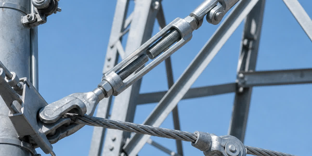
|                   \  [Heavy-Duty Drop Forged Turnbuckle]                          |
|                    \                                                              |
|                     +====== [Anchor Stay Rod / Eye Nut Assembly]                  |
|                             |                                                     |
|                      ///////|/////////////////// [Ground Level]                   |
|                             |                                                     |
|                             | Embedded Stay Rod (Hot-Dip Galvanized)              |
|                             |                                                     |
|                         [=======] Helical Screw / Expanding Anchor Plate          |
|                                                                                   |
+-----------------------------------------------------------------------------------+
2. International Standards, Material Grades & Coating Classes
Galvanized steel wire strands are specified according to strict metallurgical strength grades and zinc coating weights. Understanding these classifications ensures the correct specification matches site mechanical loads and environmental corrosion severity.
2.1 ASTM A475 & ASTM A363 Strength Classifications (7-Wire & 19-Wire)
ASTM A475 governs zinc-coated steel wire strand across five core tensile strength grades:
| ASTM A475 Grade | Nominal Tensile Strength Range (MPa / kpsi) | Typical Elongation in 610 mm (Min %) | Primary Field Application |
|---|---|---|---|
| Utilities Grade | 910 – 1,170 MPa (132 – 170 kpsi) | 4.0% | General utility distribution pole guys, messenger wires |
| Common Grade | 415 – 550 MPa (60 – 80 kpsi) | 10.0% | Low-tension guy wires, fence catenary wires, barrier cables |
| Siemens-Martin (SM) | 690 – 860 MPa (100 – 125 kpsi) | 8.0% | Distribution dead-end guys, communication tower guys |
| High Strength (HS) | 965 – 1,240 MPa (140 – 180 kpsi) | 5.0% | Heavy-duty transmission tower guying, medium-span OHGW |
| Extra High Strength (EHS) | 1,240 – 1,585 MPa (180 – 230 kpsi) | 4.0% | Ultra-high tension guy towers, long-span crossings, ASTM A363 OHGW |
2.2 Zinc Coating Weight & Galvanization Classes
The service life of galvanized steel strand is directly proportional to the thickness and mass of its zinc coating:
- ASTM A475 Class A / BS 183 / IEC 60888 Class 1: Standard hot-dip galvanized coating ($215\text{ to }300\text{ g/m}^2$ depending on wire diameter). Recommended for rural, dry, and mildly corrosive atmospheric environments (C1 to C2).
- ASTM A475 Class B / IEC 60888 Class 2: Double zinc coating weight ($430\text{ to }600\text{ g/m}^2$). Ideal for temperate industrial, sub-tropical, and coastal fringe regions (C3 to C4).
- ASTM A475 Class C: Triple zinc coating weight ($645\text{ to }900\text{ g/m}^2$). Engineered for heavy industrial chemical zones, marine splash perimeters, and severe sulfur/chloride environments (C5/CX).
+-----------------------------------------------------------------------------------+
|             STRAND CROSS-SECTION: 1x7 (6 over 1) & 1x19 (12 over 6 over 1)        |
+-----------------------------------------------------------------------------------+
|                                                                                   |
|           7-Wire Construction (1x7)                19-Wire Construction (1x19)    |
|                                                                                   |
|                   ( O ) ( O )                          ( O ) ( O ) ( O )          |
|                ( O ) ( C ) ( O )                    ( O ) ( O ) ( O ) ( O )       |
|                   ( O ) ( O )                    ( O ) ( O ) ( C ) ( O ) ( O )    |
|                                                     ( O ) ( O ) ( O ) ( O )       |
|             Center Core + 6 Outer Wires                ( O ) ( O ) ( O )          |
|                                                                                   |
|       High stiffness, optimal for guy wires      Enhanced flexibility, long-span  |
+-----------------------------------------------------------------------------------+
3. Pre-Installation Engineering Calculations & Sizing
Before commencing field work, line construction engineers must calculate the required guy strand size, lead angle, anchor uplift capacity, and safety factors in accordance with NESC Rule 261 / IEC 60826.
3.1 Guy Wire Tension Calculation
The static tension in a down-guy wire is determined by the horizontal conductor resultant load and the guy inclination angle:
$$T_{\text{guy}} = \frac{F_{\text{resultant}}}{\sin(\theta)}$$
Where: * $T_{\text{guy}}$ = Calculated tension in the guy wire strand ($\text{kN}$ or $\text{lbf}$). * $F_{\text{resultant}}$ = Total horizontal resultant force acting at the pole attachment height due to conductor line tension, dead-end pull, and transverse wind load ($\text{kN}$). * $\theta$ = Guy lead angle between the guy wire and the vertical pole ($\text{degrees}$). * $\text{Guy Lead Ratio} = \frac{\text{Lead Distance (Horizontal)}}{\text{Attachment Height (Vertical)}} = \tan(\theta)$.
+-----------------------------------------------------------------------------------+
|                   GUY TENSION AS A FUNCTION OF GUY LEAD RATIO                     |
+-----------------------------------------------------------------------------------+
|                                                                                   |
|   Pole Attachment Height (H)                                                      |
|   |  *                                                                            |
|   |  | \                                                                          |
|   |  |  \                                                                         |
|   |  |   \  Guy Wire (Tension T_guy)                                              |
|   |  |    \                                                                       |
|   |  |     \                                                                      |
|   |  | theta\                                                                     |
|   |  +-------* Anchor Point (Distance L from pole base)                           |
|                                                                                   |
|   Standard Lead Ratio (L / H = 1.0, theta = 45 deg):   T_guy = 1.414 * F_horiz    |
|   Steep Lead Ratio    (L / H = 0.5, theta = 26.6 deg): T_guy = 2.236 * F_horiz    |
|   Shallow Lead Ratio  (L / H = 1.5, theta = 56.3 deg): T_guy = 1.202 * F_horiz    |
|                                                                                   |
|   RULE: Keep theta >= 45 deg (L/H >= 1.0) whenever Right-of-Way permits to reduce  |
|         guy tension and vertical compressive buckling loads on utility poles.     |
+-----------------------------------------------------------------------------------+
3.2 Design Safety Factors (NESC Rule 261C)
- Grade B Construction (Heavy Crossing / Critical Lines): Factor of Safety $\ge 2.0$ (Guy tension under maximum wind and ice loading $\le 50\%$ of Rated Breaking Strength [RBS]).
- Grade C Construction (Standard Distribution): Factor of Safety $\ge 1.50\text{ to }1.67$ ($\le 60\%\text{ to }67\%$ of RBS).
- Initial Stringing Pre-Tension: Typically set between $10\%\text{ to }15\%$ of RBS at $15^\circ\text{C}$ to account for strand settling and structural creep.
4. Required Field Equipment, Tooling & Rigging Checklist
Executing safe and compliant installation requires certified rigging hardware and precision measurement tools:
- Tensioning & Pulling:
- Lever hoists (come-alongs) rated for minimum $20\text{ kN}$ to $50\text{ kN}$ working load limit (WLL).
- Calibrated direct-reading mechanical or digital inline dynamometer.
- Shunt-type guy wire tension meter (e.g., Dillon Quick-Check or Tensitron) calibrated specifically for 7-wire and 19-wire steel strand diameters.
- Grip & Holding Tools:
- Parallel-jaw Chicago grips or Haven grips with smooth, contoured grooves sized precisely for steel strand (never use notched conductor come-along grips which strip galvanization).
- Hydraulic cable cutters designed for high-tensile steel wire strand (avoid abrasive cutoff wheels that heat-damage zinc coatings).
- Anchoring & Torque Tooling:
- Hydraulic anchor drive motor with calibrated torque indicator for helical screw anchors.
- Deep-well socket wrenches and torque wrenches for 3-bolt guy clamps and anchor rod eye nuts.
- Inspection & Quality Instruments:
- Magnetic / eddy-current coating thickness gauge (ISO 2178 / ASTM B499 compliant).
- Earth resistance clamp meter or 3-pole Wenner test kit for grounding verification.
- Torque calibration wrench for hardware fasteners.
5. Step-by-Step Field Installation Procedure
Adhering to a standardized, eight-step installation protocol prevents strand untwisting, maintains uniform load distribution, and guarantees structural stability.
+-----------------------------------------------------------------------------------+
|                 8-STEP GALVANIZED STEEL STRAND INSTALLATION PROTOCOL               |
+-----------------------------------------------------------------------------------+
|  [Step 1: Route Survey & Anchor Point Siting]                                     |
|         |                                                                         |
|  [Step 2: Anchor Installation & Pull-Out Load Verification]                       |
|         |                                                                         |
|  [Step 3: Reel Setup, Braking & Controlled Payout]                                |
|         |                                                                         |
|  [Step 4: Pole / Tower Top Hardware Attachment]                                   |
|         |                                                                         |
|  [Step 5: Pre-Tensioning & Shunt Dynamometer Calibration]                         |
|         |                                                                         |
|  [Step 6: Anchor Termination (Preformed Grip / Wedge Dead-End)]                   |
|         |                                                                         |
|  [Step 7: Turnbuckle Final Adjustment & Insulator Insertion]                      |
|         |                                                                         |
|  [Step 8: Grounding, Electrical Bonding & Guy Guard Installation]                |
+-----------------------------------------------------------------------------------+
Step 1: Route Survey & Anchor Point Alignment
Establish the true anchor placement in direct linear alignment with the resultant phase conductor vector. Angular misalignment of the guy lead by more than $5^\circ$ introduces destructive torsional and bending moments on the utility pole. Maintain minimum clearances from roadways, driveways, underground utilities, and pedestrian zones per NESC C2.
Step 2: Ground Anchor Installation & Holding Capacity Verification
- Install helical screw anchors, plate anchors, or expanding rock anchors into undisturbed soil at the calculated lead angle.
- For helical anchors, monitor torque during installation: ultimate holding capacity is calculated via $Q_{\text{ult}} = K_t \times T_{\text{installation}}$ (where $K_t \approx 33\text{ m}^{-1}$ for standard round-shaft anchors).
- Ensure the anchor stay rod eye protrudes no more than $150\text{ to }200\text{ mm}$ above the finished ground level to minimize bending leverage under load.
Step 3: Reel Setup, Tension Braking & Payout
- Mount the galvanized steel wire strand reel on a heavy-duty payout stand equipped with a mechanical drag brake.
- Pull the strand steadily under slight back-tension. Critical Rule: Never pull strand off the flange or coil without rotating the reel; axial pulling induces permanent loops, hockles, and severe strand lay distortion.
- Keep the steel strand clear of asphalt, jagged rocks, and abrasive gravel to prevent gouging the protective zinc layer.
Step 4: Pole / Tower Top Hardware Attachment
- Secure the strand to the upper pole or tower attachment bracket using a drop-forged guy eye bolt, curved guy plate, or through-bolt thimble eye.
- Maintain a generous bending radius: the supporting thimble radius must be at least $3\times$ the strand diameter (minimum $38\text{ mm}$ for $3/8\text{ in}$ / $9.5\text{ mm}$ strand).
- For preformed dead-end grips at the top attachment, ensure the crossover marks align accurately with the thimble apex.
Step 5: Stringing, Pre-Tensioning & Settling
- Connect a smooth-jaw steel strand puller (Chicago grip) to the lower end of the strand.
- Attach a calibrated inline dynamometer and lever hoist anchored to the stay rod.
- Tension the strand to $20\%\text{ to }25\%$ of RBS for 10 minutes to seat the strand lay, compact internal contact friction, and take up initial mechanical settling ("pre-stretching").
- Back off the tension to the specified initial stringing value (typically $10\%\text{ to }12\%$ RBS at ambient temperature).
Step 6: Anchor Termination (Preformed vs. 3-Bolt Clamps)
- Preformed Dead-End Grips: Wrap the high-strength galvanized steel helical legs around the strand in accordance with manufacturer lay direction (Standard Right-Hand Lay). Ensure $100\%$ surface contact without crossover pinching or loose leg tips.
- 3-Bolt Guy Clamps: When 3-bolt clamps are specified per utility standards, install a minimum of two clamps spaced at least $150\text{ mm}$ apart. Torque all nuts uniformly to $55\text{ to }65\text{ N}\cdot\text{m}$ ($40\text{ to }50\text{ lbf}\cdot\text{ft}$).
- Install an open-jaw drop-forged steel thimble between the stay rod eye and the guy strand to prevent crushing the inner strand wires.
Step 7: Turnbuckle Adjustment & Guy Strain Insulator Insertion
- Where secondary electrical distribution or touch potential risks exist, install a fiberglass or porcelain guy strain insulator in the guy strand at a height exceeding $2.5\text{ meters}$ above ground level.
- Position a heavy-duty jaw-and-eye hot-dip galvanized turnbuckle (ASTM F1145 Class D) between the anchor dead-end and the stay rod eye. Set the turnbuckle at approximately $2/3$ extended travel to permit seasonal tension adjustments.
- Lock the turnbuckle body with safety lock wires or jam nuts to prevent rotation induced by wind vibration.
Step 8: Electrical Bonding, Grounding & Safety Guy Guards
- For overhead ground wires (OHGW), compress a parallel-groove or hydraulic compression connector from the steel strand to the tower down-lead grounding conductor. Verify earth resistance is $<10\ \Omega$ per IEEE 81.
- For down-guys on distribution poles, bond the guy wire to the multi-grounded neutral (MGN) or install an insulated guy section as specified by local codes.
- Install a high-visibility, heavy-duty yellow polyethylene guy marker (guy guard) spanning a minimum of $2.4\text{ meters}$ ($8\text{ feet}$) upward from ground level to protect the public and vehicular traffic.
6. Overhead Ground Wire (OHGW) Stringing, Sagging & Shielding Practices
Overhead ground wire installation per ASTM A363 / IEC 60888 requires specialized stringing techniques to guarantee effective lightning shielding:
- Shielding Angle: Maintain a shielding angle of $20^\circ\text{ to }30^\circ$ relative to outer phase conductors to prevent lightning shielding failures (phase strikes).
- Mid-Span Clearance Rule: Because steel strand has a lower coefficient of thermal expansion ($11.5 \times 10^{-6}\ /\ ^\circ\text{C}$) and higher modulus of elasticity ($\approx 180\text{ to }195\text{ GPa}$) compared to all-aluminum AAC conductor or ACSR conductor, OHGW sags less under maximum operating temperatures. The sag of the OHGW at mid-span under $15^\circ\text{C}$ still-air conditions should be adjusted to approximately $80\%\text{ to }90\%$ of the phase conductor sag. This ensures lightning flashover air clearance expands during peak phase conductor electrical loading.
- Vibration Dampers: Overhead ground wires are vulnerable to high-frequency aeolian vibration ($15\text{ to }70\text{ Hz}$). Install tuned Stockbridge dampers or spiral vibration dampers at calculated distances from suspension clamps to prevent strand fatigue at suspension support points.
+-----------------------------------------------------------------------------------+
|               LIGHTNING SHIELDING ANGLE & MID-SPAN SAG RELATIONSHIP                |
+-----------------------------------------------------------------------------------+
|                                                                                   |
|            [Apex: OHGW / Earth Wire]                                              |
|                   . | .                                                           |
|                  .  |  . Shielding Angle (alpha = 20 deg - 30 deg)               |
|                 .   |   .                                                         |
|                .    |    .                                                        |
|     [Phase Conductor]    [Phase Conductor] (ACSR / AAAC Phase Line)               |
|                                                                                   |
|     Mid-Span Profile:                                                             |
|     Tower Apex =================== OHGW Sag (80-90% of Phase) =================== |
|                                                                                   |
|     Crossarm   ------------------- Phase Conductor Sag (100%) ------------------- |
|                                                                                   |
|     RESULT: Air clearance between OHGW and phase conductors increases at mid-span |
|             during heavy phase electrical loading, eliminating mid-span flashover.|
+-----------------------------------------------------------------------------------+
7. Inspection, Quality Acceptance & Commissioning Verification
Prior to line energization, execute thorough quality verification against the following acceptance criteria:
| Inspection Item | Verification Method | Acceptance Standard / Tolerance | Corrective Action if Out of Spec |
|---|---|---|---|
| Guy Tension Value | Shunt dynamometer / Quick-Check meter | $\pm 10\%$ of engineered design tension | Adjust turnbuckle body to achieve target tension |
| Anchor Rod Exposure | Direct physical measurement | $150\text{ to }200\text{ mm}$ max above grade | Re-install anchor or adjust backfill grading |
| 3-Bolt Clamp Torque | Calibrated click torque wrench | $55\text{ to }65\text{ N}\cdot\text{m}$ ($40\text{ to }50\text{ lbf}\cdot\text{ft}$) | Tighten nuts to specified torque rating |
| Preformed Dead-End Fit | Visual inspection | Full 360° seating, no gaps, matched lay | Re-apply grip; replace if helix deformed |
| Zinc Coating Mass | Eddy-current coating gauge (ASTM B499) | Class A: $\ge 245\text{ g/m}^2$; Class B: $\ge 490\text{ g/m}^2$ | Reject strand drum if below standard |
| Grounding Resistance | 3-Pole Earth Tester (IEEE 81) | $< 10\ \Omega$ (Substation guys $< 1\ \Omega$) | Install additional ground rods or bentonite backfill |
| Safety Guy Guard | Physical check | Fixed $2.4\text{ m}$ height, securely anchored | Fasten locking ties or replace damaged guard |
8. Long-Term Maintenance, Corrosion Evaluation & Life Extension
Galvanized steel wire strands exposed to outdoor environments undergo progressive atmospheric degradation. Structured inspection and timely intervention extend service life beyond 40 years.
+-----------------------------------------------------------------------------------+
|               ATMOSPHERIC CORROSION TIMELINE FOR GALVANIZED STRAND                |
+-----------------------------------------------------------------------------------+
|                                                                                   |
|  [Stage 1: Years 0-10]                                                            |
|  Shiny metallic zinc -> Dull matte grey (Formation of protective zinc carbonate)  |
|  Action: Routine 2-year visual inspection. Zinc thickness loss ~1-2 um/year.      |
|                                                                                   |
|  [Stage 2: Years 10-25]                                                           |
|  Dark grey matte -> Localized white zinc rust (Zinc sacrificial depletion)        |
|  Action: Check hardware joints, torque checks, eddy-current zinc thickness audit. |
|                                                                                   |
|  [Stage 3: Years 25-35]                                                           |
|  Yellowish-brown staining -> Pinpoint red rust (Base steel exposure)              |
|  Action: Apply zinc-rich cold galvanizing paint or petrolatum tape wrap at joints.|
|                                                                                   |
|  [Stage 4: Beyond Year 35]                                                        |
|  Heavy red rust scaling -> Pitting, wire necking, broken individual wires (>5%)   |
|  Action: MANDATORY REPLACEMENT OF STRAND. Mechanical strength compromised.       |
|                                                                                   |
+-----------------------------------------------------------------------------------+
8.1 Environmental Corrosion Rates & Coating Life
| Atmospheric Environment (ISO 9223) | Typical Zinc Loss Rate ($\mu\text{m/year}$) | Class A Coating Life ($35\ \mu\text{m}$) | Class B Coating Life ($70\ \mu\text{m}$) | Class C Coating Life ($105\ \mu\text{m}$) |
|---|---|---|---|---|
| C1 / C2 (Rural / Dry Desert) | $0.2 – 0.7\ \mu\text{m/yr}$ | 50+ Years | 70+ Years | 80+ Years |
| C3 (Urban / Light Industrial) | $0.8 – 2.0\ \mu\text{m/yr}$ | 20 – 35 Years | 40 – 60 Years | 60+ Years |
| C4 (Coastal / Medium Industrial) | $2.1 – 4.0\ \mu\text{m/yr}$ | 10 – 18 Years | 20 – 35 Years | 35 – 50 Years |
| C5 / CX (Severe Marine / Chemical) | $4.1 – 10.0\ \mu\text{m/yr}$ | 4 – 8 Years | 8 – 16 Years | 15 – 25 Years |
8.2 Mandatory Replacement Criteria
Replace the galvanized steel wire strand immediately if any of the following conditions are identified during inspection:
- Broken Individual Wires: Any single broken wire in a 7-wire strand (represents a $14.3\%$ loss of cross-section and $>20\%$ loss of breaking strength due to stress concentration). In a 19-wire strand, replacement is required if two or more wires are broken in any single lay length.
- Cross-Sectional Necking: Pitting corrosion resulting in $>10\%$ reduction in nominal strand diameter.
- Severe Flaking Rust (ISO 4628-3 Ri 4 or Ri 5): Continuous red rust scaling penetrating beyond the surface into core wires.
- Anchor Creep / Uplift: Anchor rod emergence exceeding $50\text{ mm}$ above original installed height, indicating foundation shear failure.
9. Troubleshooting Field Failure Modes
| Symptom / Failure Mode | Probable Root Cause | Engineering Diagnostic | Corrective & Preventive Action |
|---|---|---|---|
| Excessive Guy Slack / Pole Tilting | Anchor soil creep, foundation slip, or uncompensated strand settling | Measure pole verticality with transit; check anchor stay rod emergence | Re-tension via turnbuckle. If anchor crept $>50\text{ mm}$, install replacement anchor at adjacent location. |
| Unequal Tension in Double Guys | Unequal guy lead distances or non-synchronized turnbuckle adjustment | Shunt dynamometer comparison between inner and outer guy strands | Balance tension evenly across both guys using twin turnbuckles ($\pm 5\%$ balance). |
| Strand Slippage in 3-Bolt Clamp | Insufficient bolt torque or contaminated/greased strand surface | Visual witness marks on strand paint line | Re-align strand, clean contact surfaces, torque bolts to $65\text{ N}\cdot\text{m}$, install second clamp. |
| Accelerated Corrosion at Ground Level | Soil-air interface galvanic reaction, standing water, lawn mower impacts | Inspect stay rod interface $100\text{ mm}$ above and below ground line | Install heavy-duty polyethylene sleeve or petrolatum anti-corrosion tape; replace corroded stay rod. |
| Broken Wires at Suspension Clamp | High-frequency aeolian vibration fatigue | Ultrasonic / eddy-current testing at clamp mouth | Install Stockbridge or spiral vibration dampers; install protective armor rods beneath suspension clamps. |
| Deformed / Hockled Strand | Axial twist during unreeling from stationary spool | Visual kink, loosened outer wire lay | Cut out deformed section entirely; splice using preformed full-tension splices or replace span. |
10. Personnel Safety & Standards Compliance
Field installation of steel wire strand involves substantial stored mechanical energy and proximity to energized conductors:
- High-Tension Recoil Hazard: When cutting steel strand under tension or releasing come-alongs, the strand can whip violently. Always install temporary safety grip holdbacks and stand clear of the tension line of fire.
- Overhead Electrical Hazard: Uncontrolled payout of steel strand near live overhead distribution lines poses extreme electrocution hazards. Bond all stringing equipment to earth ground and maintain minimum approach distances (MAD) per OSHA 1910.269 / NESC Table 441-1.
- Personal Protective Equipment (PPE): Mandate safety glasses with side shields, heavy leather rigging gloves, steel-toed boots, and class E electrical hard hats for all crew members.
11. Frequently Asked Questions (FAQ)
Q1: What is the difference between ASTM A475 and ASTM A363 steel strand?
A: ASTM A475 covers general-purpose zinc-coated steel wire strand used predominantly for guy wires, stay wires, and aerial messenger cables, providing five strength grades (Utilities, Common, Siemens-Martin, High Strength, Extra High Strength). ASTM A363 specifically covers high-purity galvanized steel strand intended exclusively for overhead ground wire (earth/shield wire) in electrical transmission lines, with tighter electrical conductivity and weldless wire stranding requirements.
Q2: What is the standard lay direction for galvanized steel guy strand?
A: The standard lay direction for galvanized steel wire strand is Right-Hand Lay (RHL) unless explicitly specified otherwise. All preformed dead-ends, guy grips, and full-tension splices must match the exact strand lay direction to ensure uniform 360-degree frictional gripping.
Q3: Why should I never use a notched conductor come-along on steel strand?
A: Conductor grips designed for aluminum wires (AAC conductor or ACSR conductor) frequently feature notched or serrated jaws. When applied to steel strand, these serrations bite through the soft zinc coating, exposing raw high-carbon steel to rapid galvanic oxidation and creating stress-concentration notches that trigger premature tensile failure. Always use smooth, parallel-groove steel strand grips (Chicago-style grips).
Q4: How is the holding capacity of a helical screw anchor calculated?
A: The ultimate holding capacity ($Q_{\text{ult}}$) of a helical anchor installed in soil is directly proportional to the installation torque: $Q_{\text{ult}} = K_t \times T$, where $T$ is the final installation torque ($\text{N}\cdot\text{m}$ or $\text{lbf}\cdot\text{ft}$) and $K_t$ is the anchor torque factor (typically $33\text{ m}^{-1}$ for standard round-shaft power utility anchors).
Q5: When should a guy strain insulator be installed?
A: Guy strain insulators (manufactured from wet-process electrical porcelain or fiberglass-reinforced polymer) must be inserted into guy wires on poles carrying energized power lines whenever there is a risk of contact between an energized phase and the guy wire, or to prevent hazardous step and touch potentials accessible to the general public within $2.5\text{ meters}$ ($8\text{ feet}$) of the ground.
Q6: Can galvanized steel wire strand be welded or soldered?
A: No. Welding, brazing, or high-temperature soldering anneals the high-carbon steel wire, drastically reducing its tensile strength by $50\%\text{ to }70\%$ and destroying the protective zinc galvanization. All joints and terminations must be executed with drop-forged compression hardware, preformed helical fittings, or wedge dead-ends.
Q7: How does guy lead ratio affect pole buckling?
A: A steeper guy wire (smaller horizontal lead distance $L$ relative to attachment height $H$) results in much higher strand tension and introduces a massive downward vertical compressive load on the utility pole. A lead ratio of $L/H = 1.0$ ($\theta = 45^\circ$) is the industry standard; ratios below $0.5$ ($\theta < 26.6^\circ$) significantly increase the risk of pole buckling under heavy wind and ice conditions.
Q8: What is the expected lifespan of Class A vs. Class C galvanized strand in coastal areas?
A: In coastal marine environments (ISO 9223 C4/C5 classification with zinc corrosion rates of $2.5\text{ to }6.0\ \mu\text{m/year}$), standard Class A galvanization ($35\ \mu\text{m}$ zinc) provides approximately $6\text{ to }14\text{ years}$ of protection before red rust appears. Class C galvanization ($105\ \mu\text{m}$ zinc) extends service life to $20\text{ to }40\text{ years}$ under the same corrosive exposure.
12. International Standards & Technical References
| Standard Code | Standard Title & Scope |
|---|---|
| ASTM A475 | Standard Specification for Zinc-Coated Steel Wire Strand |
| ASTM A363 | Standard Specification for Zinc-Coated (Galvanized) Steel Overhead Ground Wire Strand |
| BS 183 | Specification for General Purpose Galvanized Steel Wire Strand |
| IEC 60888 | Zinc-Coated Steel Wires for Stranded Conductors |
| EN 50189 | Conductors for Overhead Lines - Zinc Coated Steel Wires |
| IEEE 524 | IEEE Guide to the Installation of Overhead Transmission Line Conductors |
| NESC C2 | National Electrical Safety Code (Part 2: Safety Rules for Overhead Lines) |
| ISO 1461 | Hot Dip Galvanized Coatings on Fabricated Iron and Steel Articles |
| ASTM F1145 | Standard Specification for Turnbuckles, Swaged, Welded, Forged |
| IEEE 81 | IEEE Guide for Measuring Earth Resistivity, Ground Impedance, and Earth Surface Potentials |
Related Products & Engineering Support
SiTong Cable manufactures premium-grade hot-dip galvanized steel wire strands, stay wires, and overhead ground wires engineered to meet ASTM A475, ASTM A363, BS 183, and IEC 60888 specifications with customized strand constructions, coating classes (Class A, B, C), and complete hardware accessory packages.
👉 Browse our Galvanized Steel Wire product range 👉 Galvanized Steel Wire Strand: Complete Technical Guide & Selection 👉 Contact our engineering and procurement team for technical inquiries
📬 Sales inquiries: sales@sitongcable.com | 📞 Phone: +86-371-69176007